
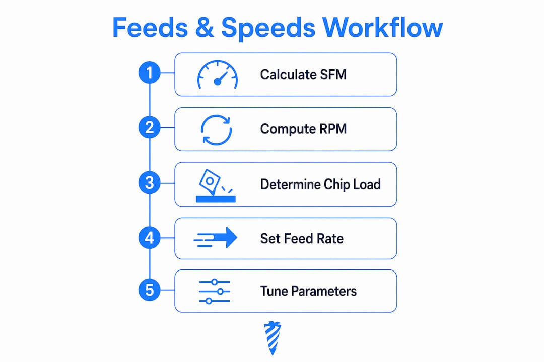
To calculate feeds and speeds, you need two formulas: RPM = (SFM × 3.82) ÷ tool diameter (inches) and Feed Rate (IPM) = RPM × chip load (in/tooth) × number of flutes. Run those in three steps: look up the recommended surface feet per minute (SFM) for your material and tool, convert to RPM, then multiply out your feed rate and check it against your machine's spindle and power limits.
Here's the workflow at a glance:
- Step 1 — Choose SFM: Pull the recommended cutting speed from a chip-load table or tool manufacturer's data sheet for your material/tool combination.
- Step 2 — Calculate RPM: Divide (SFM × 3.82) by your cutter diameter in inches.
- Step 3 — Calculate IPM and verify: Multiply RPM × chip load × flute count, then confirm the result is within your spindle's power and torque range.
For quick verification, the Kennametal Speeds and Feeds Calculator, the LittleMachineShop Machinists Calculator, and the Availzye Machinist Pro feeds & speeds calculator all let you cross-check a number in under a minute.
Table of Contents
- What every variable means and how the formulas work
- Step-by-step worked examples with real numbers
- Chip-load reference tables for common materials and cutter types
- How to tune theoretical numbers to your actual machine
- Which calculator or tool fits your situation?
- Quick-reference cheat sheet for the shop floor
- Key Takeaways
- The tradeoff nobody talks about enough
- What Availzye Machinist Pro does for your feeds & speeds workflow
- Useful sources and further reading
What every variable means and how the formulas work
SFM (Surface Feet per Minute) is the speed at which the cutting edge moves across the workpiece surface. It depends on the tool material and workpiece material, not on your machine's spindle directly. Carbide runs at higher SFM than HSS; aluminum tolerates far higher SFM than stainless steel.

RPM is the spindle speed your machine actually turns. You derive it from SFM and tool diameter. The imperial formula is:
The constant 3.82 is simply 12 ÷ π, the conversion factor between linear surface speed and rotational speed in imperial units. In metric, the equivalent is RPM = (1000 × V) ÷ (π × D), where V is in m/min and D is in mm.
Chip load (IPT) is the amount of material each cutting edge removes per revolution, measured in inches per tooth. Too low and you're rubbing instead of cutting; too high and you're snapping tools.
Feed Rate (IPM) is how fast the cutter advances through the part. The feed rate formula is:
Number of flutes is the count of cutting edges on your end mill or drill. More flutes mean a higher feed rate at the same chip load, but they also leave less room for chip evacuation, which matters a lot in aluminum.
Unit conversion quick reference
| Convert | From | To | Formula |
|---|---|---|---|
| SFM to m/min | ft/min | m/min | × 0.3048 |
| m/min to SFM | m/min | ft/min | — |
| Inches to mm | in | mm | × 25.4 |
| mm to inches | mm | in | ÷ 25.4 |
| IPM to mm/min | in/min | mm/min | × 25.4 |
Common unit traps to avoid:
- Mixing metric and imperial tool diameters in the same formula (always convert first)
- Reading a drawing's surface finish callout in μm when the shop standard is μin — ASME Y14.36 governs US drawings, while ISO 1302 is the international standard; always check the title block
- Using the workpiece diameter for milling instead of the cutter diameter (only turning uses workpiece diameter)
Step-by-step worked examples with real numbers
Milling example: 1/2" carbide end mill in aluminum
Example setup: 1/2" diameter, 4-flute carbide end mill milling 6061 aluminum. Recommended SFM for carbide in aluminum can vary; a mid-range starting point is often chosen around the middle of the typical range.
- RPM = (800 × 3.82) ÷ 0.500 = 3,056 ÷ 0.500 = 6,112 RPM
- Chip load for a 1/2" carbide end mill in aluminum: 0.004" per tooth (from table below)
- Feed Rate = 6,112 × 0.004 × 4 = 97.8 IPM
Round to 6,100 RPM and 95 IPM to stay within a comfortable margin. Before running it, confirm your spindle can actually deliver torque at 6,100 RPM and that your workholding is solid enough for nearly 100 IPM. If the machine sounds strained or the chips come out as fine dust instead of curls, back the feed down 20% first.
The constant 3.82 = 12 ÷ π. It converts surface feet per minute into the rotational speed needed at a given diameter. Every imperial RPM calculation uses it, so it's worth memorizing.
Turning example: 2" diameter steel bar on a lathe
Example setup: 2" diameter 1018 mild steel bar with carbide insert, target SFM chosen for operations.
- RPM = (400 × 3.82) ÷ 2.000 = 1,528 ÷ 2.000 = 764 RPM
- Feed per revolution for a finishing pass: 0.008 in/rev
- Feed Rate (IPM) = 764 × 0.008 = 6.1 IPM
For a roughing pass, increase feed per revolution according to roughing chip load guidelines. and watch chip color. Blue or purple chips on steel mean the cutting speed is too high or coolant isn't reaching the cut. Calculated numbers are starting estimates; machine-specific limits always require field adjustments.
Chip-load reference tables for common materials and cutter types
These are starting values. Adjust for operation type, stepover, and depth of cut before committing to a production run.
Carbide end mill chip loads (inches per tooth)
| Material | — | 1/4" dia | 1/2" dia | 3/4" dia |
|---|---|---|---|---|
| Aluminum (6061) | 0.001–0.002 | 0.002–0.004 | 0.004–0.006 | 0.004 |
| Mild steel (1018) | 0.0007 | 0.001–0.002 | 0.002–0.003 | 0.003–0.004 |
| Alloy steel | 0.0007 | 0.001 | 0.002 | 0.002–0.003 |
| Stainless | 0.0007 | 0.001 | 0.001–0.002 | 0.002 |
| Titanium (Ti-6Al-4V) | 0.0003 | 0.0007 | 0.001 | 0.002 |
| Brass | 0.001–0.002 | 0.002–0.004 | 0.003 | 0.004–0.006 |
| Plastics (Delrin/Nylon) | 0.002–0.004 | 0.003–0.006 | 0.004 | 0.006–0.010 |
HSS vs. carbide and coating notes
HSS tools run at roughly 25–40% of the SFM you'd use for carbide in the same material. A carbide end mill in aluminum might run at 800 SFM; an HSS end mill in the same material tops out around 200–300 SFM. Coatings change the picture: TiAlN-coated carbide handles higher temperatures and can push SFM up 20–30% in steels, while uncoated carbide in aluminum is often preferred because TiAlN can cause built-up edge on that material. ZrN or DLC coatings are the better choice for aluminum.
Chip-load tables give starting values; finishing and roughing require different targets. A finishing pass typically uses 50–70% of the roughing chip load to improve surface finish.
Pro Tip: For tool stickout longer than 3× the cutter diameter, reduce chip load by 20–30% and consider dropping RPM by 10–15%. Long overhangs amplify deflection, and the tool deflection calculator in Availzye Machinist Pro can quantify exactly how much flex you're introducing before you cut.
Red flags that tell you to back off immediately:
- Chatter marks or vibration you can feel through the table
- Chips turning blue or purple (excessive heat)
- Squealing or high-pitched tone from the spindle
- Rapid tool wear or edge chipping after just a few passes
- Fine powder instead of chips (rubbing, not cutting)
How to tune theoretical numbers to your actual machine
Formulas give you a baseline. Your machine, workholding, and setup determine whether that baseline is safe or reckless.
Checklist before you run:
- Confirm spindle power and torque at your target RPM. Many machines lose torque significantly above 60–70% of max RPM.
- Check tool stickout. Shorter is always better; minimize it to the job requirements.
- Verify workholding rigidity. A part that shifts at 50 IPM will shift worse at 100 IPM.
- Set depth and width of cut deliberately. Full-width slotting at full depth is the worst-case load; reduce one or both if your machine is at its limit.
- Confirm coolant reach. Flood coolant that doesn't hit the cut is decoration.
Common tuning actions:
- Chatter: reduce chip load first (not RPM), then try a different RPM to move out of a resonant frequency
- Thin-walled work: increase RPM and reduce chip load to lower cutting forces
- Deep plunges or full-slot cuts: reduce feed rate 30–50% from your calculated IPM
- Tool heating without chip color change: check coolant flow and consider a coated tool
Pro Tip: Change one variable at a time and write it down. A machinist who records "6,000 RPM, 90 IPM, 0.050" DOC, good chips, no chatter" has a repeatable process. One who doesn't is starting from scratch every run. Audible cues and chip formation are your most reliable real-time diagnostics — trust them over the formula when they disagree.
As a tool wears, cutting forces rise. If you're tracking tool life, experienced machinists recommend reducing feed rate by 10–15% as a tool approaches end-of-life rather than running it to failure. The chip thinning calculator is worth checking when you change stepover, since CAM-suggested chip loads assume a specific radial engagement.
Which calculator or tool fits your situation?
Not every job needs the same level of tooling. Here's how to match the tool to the task:
- Simple web calculators (Kennametal, LittleMachineShop, CustomPartNet Milling Speed and Feed calculator, OmniCalculator Speeds and Feeds): best for quick one-off checks. Enter SFM, diameter, and chip load; get RPM and IPM in seconds. No account needed, no history saved.
- CAM-integrated feeds & speeds: tools like Fusion 360's built-in library or Mastercam's tool database pull parameters automatically from your tool library. Good for toolpath-level optimization, but the quality depends entirely on how well your tool library is maintained.
- Cloud SaaS platforms: the right choice when you need repeatability across operators, shifts, or machines. A platform that stores your tool database, logs what parameters actually worked, and flags when a tool is approaching end-of-life turns a one-time calculation into a shop standard.
The switch from a quick calculator to a production tool makes sense when you're running the same job more than twice, when multiple operators touch the same machine, or when you need traceability for quality records.
Availzye Machinist Pro sits in the third category. Its feeds & speeds calculator handles the SFM→RPM→IPM math, but it connects directly to a tool database that stores your preferred parameters per tool and material. The G-Code Wizard and G-Code Generator let you push verified parameters directly into programs. Add Tool Crib inventory tracking and tool-life logging, and you have a system where a new operator on second shift runs the same parameters as the experienced machinist who set them up.
Quick-reference cheat sheet for the shop floor
Pin this at the mill or lathe.
Core formulas:
- RPM = (SFM × 3.82) ÷ D (inches)
- Feed Rate (IPM) = RPM × chip load (IPT) × flutes
- Metric RPM = (1000 × V m/min) ÷ (π × D mm)
Conversion constants:
- 3.82 = 12 ÷ π (imperial RPM constant)
- 1 inch = 25.4 mm | 1 SFM = 0.3048 m/min
Common starting chip loads (carbide):
- Aluminum: 0.002–0.006" (scales with diameter)
- Mild steel: 0.001–0.003"
- Stainless: 0.0007–0.002"
- Plastics: 0.003–0.010"
Five quick tuning rules:
- Chatter? Reduce chip load first, then try a different RPM.
- Blue chips on steel? Cut SFM by 15–20% or add coolant.
- Tool rubbing (powder, no chips)? Increase chip load or SFM.
- Long stickout (>3× D)? Drop chip load 20–30%.
- Finishing pass? Use 50–70% of your roughing chip load.
Before any aggressive MRR run: verify units on the drawing title block (ASME Y14.36 vs. ISO 1302), confirm spindle torque at your target RPM, and check that coolant reaches the cut. Save this sheet as a PDF and upload it to your shop's document management system or the Availzye Machinist Pro document library so every operator has access.
Key Takeaways
Accurate feeds and speeds come from applying the SFM→RPM→IPM workflow, treating the result as a baseline, and tuning from there based on your machine, tooling, and what the chips tell you.
| Point | Details |
|---|---|
| Core formulas | RPM = (SFM × 3.82) ÷ D; Feed Rate (IPM) = RPM × chip load × flutes. |
| Treat numbers as baselines | Calculated values require field adjustment for spindle power, stickout, and workholding. |
| Watch the chips | Chip color, sound, and formation are more reliable real-time diagnostics than any formula. |
| Check your units | Confirm whether the drawing uses ASME Y14.36 or ISO 1302 before setting finish-driven parameters. |
| Availzye Machinist Pro | Connects feeds & speeds calculations to a tool database, tool-life tracking, and G-code output for repeatable shop standards. |
The tradeoff nobody talks about enough
The conventional wisdom is to maximize material removal rate (MRR) and let tool life sort itself out. That's the wrong priority for most shops.
MRR is easy to measure. Tool life is easy to ignore until a broken end mill scraps a $400 part. The shops that run the tightest cost-per-part numbers aren't the ones pushing the highest feed rates. They're the ones who found a parameter set that produces consistent chips, predictable tool life, and acceptable surface finish, then locked it in and stopped experimenting on production parts.
The surface finish side of this is underappreciated. A general-purpose turned or milled surface is often specified at A general-purpose turned or milled surface is often specified near this roughness range. Bearing and hydraulic bore surfaces require much lower Ra values, and here's where feed rate directly controls the outcome. Reduce feed per revolution on a lathe and Ra drops. But Ra alone can be misleading: Rz captures peak-to-valley height and matters far more for sealing surfaces than the arithmetic average Ra does. Chasing an Ra number while ignoring Rz is how a hydraulic fitting passes inspection and then leaks in the field.
The practical philosophy: calculate your baseline, run a trial cut, record what worked, and build a per-machine parameter set. Not a global spreadsheet, a per-machine one, because a 10-year-old Haas and a new DMG have different torque curves, different rigidity, and different spindle bearings. Availzye Machinist Pro's tool database and job-level tracking make that recordkeeping automatic rather than dependent on one machinist's notebook.
What Availzye Machinist Pro does for your feeds & speeds workflow
Every machinist eventually outgrows a one-off calculator. When you're running the same materials and tools across multiple jobs, the real cost isn't the 30 seconds to punch numbers into a web form. It's the 20 minutes of re-establishing what worked last time, or the scrapped part when someone used last month's parameters on a worn tool.

Availzye Machinist Pro gives you a feeds & speeds calculator that connects directly to your tool database, so the chip loads and SFM values you verified last week are already loaded when you set up the next job. The Power & Torque and Tool Deflection checks run alongside the feed calculation, so you catch a problem before the spindle does. The G-Code Wizard and G-Code Generator push verified parameters into your programs, and the Tool Crib tracks tool life so you know when to adjust feed before a tool fails. Three subscription tiers start at $9.99/month, with a 7-day free trial. Start the trial, import your tool list, and run your first calculation in under five minutes.
Useful sources and further reading
Good feeds and speeds work starts with reliable references. Here's where to look:
- Fablab Speed and Feeds Calculator (MIT CBA): a clean, no-account calculator useful for quick SFM→RPM→IPM checks across common materials and operations.
- Kennametal Speeds and Feeds Calculator: manufacturer-grade data for Kennametal tooling; use it when you're running their inserts and want parameters straight from the source.
- OmniCalculator Speeds and Feeds: covers milling, turning, drilling, and reaming in one tool with both preset and manual modes.
- ASME Y14.36: the US standard for surface finish symbols on technical drawings. Check the drawing's title block to confirm whether ASME Y14.36 or ISO 1302 governs before selecting feed/speed for a finish-critical operation. When the standard matters, go to the primary document, not a summary blog.
- Tool manufacturer data sheets: always the first reference for chip load and SFM. Manufacturer values account for coating, geometry, and substrate in ways that generic tables can't.
- Availzye Machinist Pro surface finish calculator: translates drawing Ra/Rz callouts into machining targets and helps connect finish requirements back to feed rate choices.
A note on standards: when a drawing specifies a surface finish, confirm whether the value is in μm or μin before selecting your feed rate. Ra 3.2 μm and Ra 3.2 μin are not the same number. Confusing the two is a common and costly shop mistake. For cross-disciplinary reference on how governing standards and unit consistency apply across engineering documents, the guidance on checking governing standards in other technical fields reinforces the same principle: always confirm the standard before you commit to a number.