
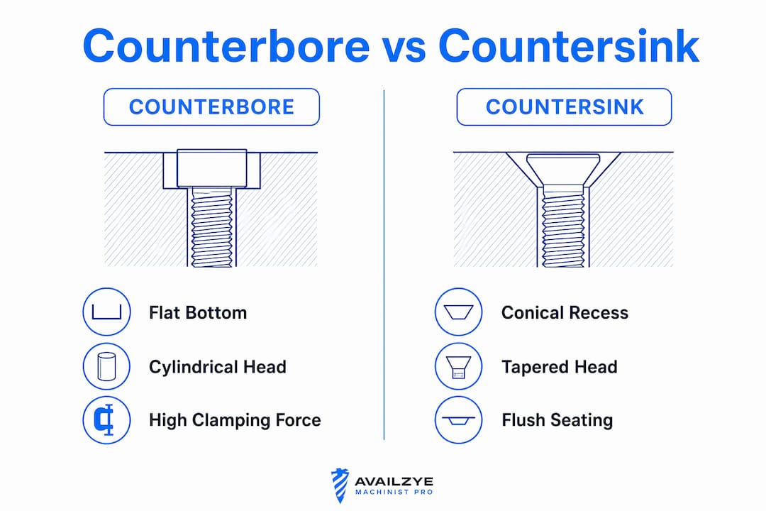
A countersink (⌵) is a conical recess for tapered-head screws; a counterbore (⌴) is a flat-bottomed cylindrical recess for socket-head cap screws and hex bolts. The core distinction is fastener head geometry: if the head is tapered, you need a countersink; if it's cylindrical, you need a counterbore.
Three rules cover most shop decisions. Use a counterbore when you need high clamping force, repeated disassembly, or a socket-head cap screw seated below the surface. Use a countersink when a flat-head screw must sit flush for aerodynamics, aesthetics, or a smooth surface. And watch thin-wall parts carefully: both features remove material and can weaken a thin plate, but a deep countersink removes an exponentially growing cone of material as it deepens.
Table of Contents
- What is a countersink, and which fasteners does it fit?
- What is a counterbore, and when does a flat bottom matter?
- How do counterbore and countersink compare side by side?
- When should you use a countersink vs. a counterbore?
- How do you cut a countersink or counterbore in the shop?
- How to annotate countersinks and counterbores on drawings
- Common mistakes and how to fix them
- Using a counterbore calculator: a worked sizing example
- Key Takeaways
- The tradeoff nobody talks about enough
- Availzyemachinistpro Counterbore Calc cuts setup time and scrap
- Useful sources and references
What is a countersink, and which fasteners does it fit?
A countersink is a conical recess machined at the entrance of a drilled hole. Its purpose is simple: the tapered walls match the angled underside of a flat-head screw, letting the head sit flush with or just below the workpiece surface.
Common included angles and their standards:
- 60° — used for center-drilling, some wood screws, and deburring operations
- 82° — the ANSI standard for inch flat-head screws; the most common angle in American shops
- 90° — the ISO/metric standard; used for metric flat-head screws throughout Europe and in most CNC programs written to ISO standards
- 100°, 110°, 120° — found in aerospace fasteners, sheet-metal rivets, and specialty hardware where shallower head profiles are needed
Mixing 82° and 90° is one of the most common failure points in mixed-standard shops. The screw head either rocks on the cone lip or pulls down unevenly, creating a stress concentration at the thread root. If your shop runs both ANSI and metric hardware, label your countersink bits clearly and keep them in separate drawers.
Countersink diameter is sized to match the fastener's major head diameter, and depth is set so the head sits flush or just below flush. Shallow sinks work fine for wood and soft plastics; in metals, going too shallow leaves the head proud, while going too deep removes material unnecessarily and can weaken thin stock.
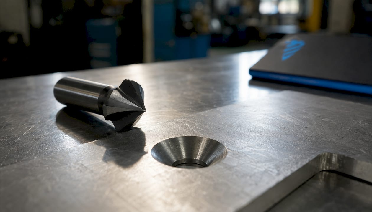
One terminology note worth getting right: countersink refers to the feature or the tool; countersunk describes the state of a fastener after it's been installed. Confusing the two often leads to specifying the wrong angle on a drawing. On engineering drawings, the countersink is called out with the ⌵ symbol followed by the included angle and major diameter.
What is a counterbore, and when does a flat bottom matter?
A counterbore is a cylindrical, flat-bottomed recess that enlarges the top of a drilled hole to a larger diameter. Unlike a countersink, the walls are vertical and the bottom is perfectly flat. That flat bottom is the whole point: it gives a cylindrical fastener head a uniform bearing surface so clamping force distributes evenly across the contact area.
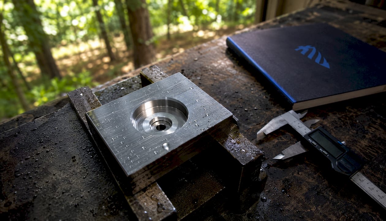
The typical fasteners for counterbores are socket-head cap screws, hex bolts, and any bolt used with a washer. The socket-head cap screw is the workhorse of precision machinery for exactly this reason: its cylindrical head drops into the counterbore, the flat underside bears on the flat bottom, and you get a clean, predictable load path.
Concentricity matters here. A counterbore cutter uses a pilot that rides in the through-hole to keep the counterbore centered on the pilot hole. If you're using an endmill instead, you need to spot the center accurately before enlarging. Misaligned counterbores cause the screw head to bear unevenly, which defeats the purpose.
Sizing basics: counterbore diameter is typically the fastener head diameter plus a small clearance (0.2–0.5 mm is common practice). Depth equals the head height, with a small addition so the head sits just below the surface. A spotface is a shallow version of a counterbore, usually just deep enough to clean up a rough casting surface and give the fastener a flat seat — it doesn't recess the head below the surface. On drawings, counterbores use the ⌴ symbol; spotfaces are typically called out as "SF" with a diameter.
How do counterbore and countersink compare side by side?
The mechanical consequences of choosing one over the other go well beyond shape.
| Feature | Countersink ⌵ | Counterbore ⌴ |
|---|---|---|
| Geometry | Conical recess, angled walls | Cylindrical recess, vertical walls, flat bottom |
| Compatible fasteners | Flat-head screws, countersunk rivets | Socket-head cap screws, hex bolts, washered bolts |
| Material removed | Cone volume — grows rapidly with depth | Uniform cylinder — predictable volume |
| Load path | Axial + radial; force transmitted at an angle | Primarily axial; flat surface spreads load evenly |
| Tolerance sensitivity | High — angle must match fastener head exactly | Lower — clearance on diameter and depth is forgiving |
| Thin-wall risk | High — deep cone removes a lot of material fast | Moderate — cylindrical pocket reduces section thickness uniformly |
| Assembly tolerance | Tight; burrs prevent flush seating | Forgiving; head drops in as long as diameter clears |
| Drawing symbol | ⌵ (angle × major diameter) | ⌴ (diameter × depth) |
| Typical applications | Aerospace panels, furniture, sheet metal, electronics | Machine frames, molds, serviceable assemblies |
Key mechanical tradeoffs:
- A flat-bottomed counterbore distributes clamping force more evenly than a tapered seat, making it the better choice for high-load or dynamically loaded joints.
- Deep countersinks remove rapidly increasing material volume and can significantly weaken thin plates; counterbores remove a uniform cylinder but still reduce effective section thickness if over-deepened.
- Countersinks are more sensitive to angle mismatch. A 2° error in a countersink produces a line contact instead of surface contact; a counterbore with 0.3 mm extra diameter still seats the fastener correctly.
- Countersinks are faster and cheaper to produce on sheet products, which is why they dominate woodworking and sheet-metal work where deep material removal is undesirable.
When should you use a countersink vs. a counterbore?
The decision usually comes down to four factors: fastener type, load, maintenance frequency, and aesthetics.
-
Flush surface required (countersink): Aerospace panels, consumer electronics housings, and furniture faces all need a smooth surface. A flat-head screw in a properly sized countersink delivers that. If the surface will be painted, anodized, or bonded, a countersink keeps the fastener from creating a bump.
-
High clamping load (counterbore): Machine frames, mold bases, and structural joints need reliable clamping force. Socket-head cap screws in counterbores give you that flat bearing surface and the torque capacity to generate high preload.
-
Frequent disassembly (counterbore): If a panel or cover comes off regularly for maintenance, socket-head cap screws in counterbores hold up better. The flat seat doesn't wear the way a tapered countersink can when a screw is run in and out repeatedly.
-
Thin sheet metal (countersink, with caution): Sheet metal under about 0.125" is usually too thin for a counterbore. A countersink is the practical choice, but keep the depth conservative. Going too deep on thin stock removes most of the material around the hole.
-
Plastics: Countersinks work in plastics but require the springback allowance described below. Brittle materials like acrylic or PEEK are better served by counterbores because the conical recess generates radial stress that can crack brittle stock.
-
Wood and composites (countersink): Wood screws are almost always flat-head, so countersinks are standard. In composites, countersinks are common for flush fastening, but the depth must be controlled tightly to avoid delamination.
-
Can you counterbore with a regular drill bit? No. A standard twist drill produces a conical point at the bottom, not a flat one. Using a twist drill to "counterbore" leaves a pointed recess that prevents the fastener head from seating uniformly. Use a counterbore cutter, spotface tool, or endmill instead.
-
Button-head and oval-head screws: Button-head socket screws have a low-profile domed head that sometimes seats in a shallow counterbore or sits proud by design. Oval-head screws use a countersink for the tapered underside but leave the dome above the surface. Know your fastener's head geometry before specifying either feature.
How do you cut a countersink or counterbore in the shop?
Tooling options
For countersinks: single-flute countersink bits, multi-flute countersink bits (3–6 flutes for smoother finish in metals), and combination drill/countersink tools that drill and sink in one pass. Multi-flute bits chatter less in metals; single-flute bits are fine for wood and plastics.
For counterbores: dedicated counterbore cutters with a pilot pin, spotface cutters, and endmills. Endmills are the most flexible option on a mill or CNC, but they require accurate centering. Dedicated counterbore cutters with a pilot are faster and self-aligning on a drill press.
Procedure on a drill press
- Drill the pilot (through) hole to the specified clearance diameter.
- Install the countersink bit or counterbore cutter. For a counterbore cutter, select the pilot diameter that matches your through-hole.
- Set depth stop. For countersinks, use a test piece and check with the actual fastener. For counterbores, set depth to head height plus your clearance allowance.
- Cut at a moderate feed. Countersinks in metal benefit from a slow, steady feed to avoid chatter. Counterbore cutters need firm, consistent pressure to keep the pilot engaged.
- Deburr. Countersinks especially need clean edges; a burr at the rim prevents flush seating.
On a mill or CNC
Spot the center, drill the pilot hole, then run the countersink or counterbore operation. On CNC, use canned cycles where available, or a simple G81/G82 with the correct depth. Carbide tooling is preferred for aluminum and harder metals; HSS works for mild steel and plastics at lower speeds.
Pro Tip: After cutting, drop the actual fastener into the feature and check seating by feel and by running a straightedge across the head. For production work or critical assemblies, verify counterbore diameter with a plug gauge and depth with a depth micrometer. G-code depth alone doesn't account for tool deflection or runout, which can shift effective depth by several thousandths.
How to annotate countersinks and counterbores on drawings
Callout formats
Countersink: ⌵ followed by the included angle and major diameter. Example: ⌵82° × Ø0.375. If depth is critical, add it after the diameter. The pilot hole callout precedes the countersink callout on the same leader line.
Counterbore: ⌴ followed by diameter and depth. Example: ⌴Ø0.500 ↧ 0.250. The pilot hole diameter appears on the same leader, typically above the counterbore callout.
Spotface: Call out as SF Ø[diameter] with depth noted only if controlled. A spotface with no depth specified means "machine until flat."
Tolerance guidance
Standard shop practice adds clearance to fastener nominals to account for coating thickness, part variation, and assembly ease. Typical allowances:
| Dimension | Typical clearance tolerance | Notes |
|---|---|---|
| Counterbore diameter | +0.012" to +0.031" over nominal | Wider for coated or plated fasteners |
| Counterbore depth | +0.005" to +0.020" over nominal | Prevents head from protruding |
| Countersink major diameter | Match fastener head diameter ±0.005" | Tighter tolerance for flush-critical surfaces |
| Pilot hole diameter | Clearance fit per ANSI/ISO standard | Loose, normal, or close fit per application |
For metric sizing, ANSI metric counterbore tables give pilot hole, counterbore diameter, and depth per nominal screw size. An M2 normal-fit counterbore, for example, calls for a 2.4 mm pilot, 4.4 mm counterbore diameter, and 2.5 mm depth.
Surface finish
Bearing surfaces under fastener heads should be specified at Ra 125 µin (3.2 µm) or better for standard assemblies. High-load or fatigue-critical joints often call for Ra 63 µin (1.6 µm). A rough bearing surface concentrates stress at asperities and reduces effective clamping area. The surface finish calculator in Availzyemachinistpro can help you specify and verify Ra targets for these features.
Common mistakes and how to fix them
Wrong countersink angle. Using an 82° bit on a 90° metric screw (or vice versa) produces either a proud head or a rocking fit. The fix is straightforward: identify your fastener standard before you cut, and keep ANSI and ISO bits physically separated in your tool crib.
Using a twist drill to counterbore. The conical tip leaves a pointed bottom that prevents flat seating. Scrap the part or rework with a proper counterbore cutter or endmill.
Over-deep countersink in thin stock. The head drops below the surface and the surrounding material is paper-thin. Prevention: set depth stop conservatively and check with a fastener before committing. Rework options are limited; in metals you can sometimes fill with weld and re-machine, but thin sheet usually gets scrapped.
Springback in soft materials. Aluminum, soft plastics, and wood spring back slightly after the tool retracts, leaving the countersink shallower than cut. Cut countersinks 0.003"–0.005" deeper than theoretical in soft materials to compensate. Verify with the actual fastener, not just a depth gauge.
Counterbore not concentric with pilot hole. Caused by a worn or undersized pilot pin, or by using an endmill without spotting first. The fastener head bears on one side only. Fix: re-machine with a fresh pilot or re-spot the center.
Burrs at the countersink rim. Even a small burr prevents flush seating. Always deburr after cutting, and re-check with the fastener.
Inspection checklist before assembly:
- Drop the fastener in and check that the head sits at or below the surface.
- Run a straightedge across the head for flush-critical surfaces.
- For production: check counterbore diameter with a plug gauge and depth with a depth micrometer.
- Verify concentricity visually or with a dial indicator if alignment is critical.
Using a counterbore calculator: a worked sizing example
A repeatable, calculator-driven process standardizes sizing across a team and reduces assembly errors compared to manual one-off lookups. Here's how to run it for a common fastener.
Worked example: 3/8-16 socket-head cap screw, normal fit, mild steel, uncoated
- Identify the fastener: 3/8" nominal diameter, socket-head cap screw, ANSI Inch standard.
- Look up or calculate pilot hole: 25/64" (close fit) or 13/32" (normal fit). For a normal fit, use 13/32".
- Counterbore diameter: 5/8" (from ANSI Inch counterbore tables for 3/8" socket-head cap screw).
- Counterbore depth: 3/8" nominal head height. Add +0.005" to +0.020" depth clearance. Target depth: 0.395"–0.410".
- Diameter clearance check: 5/8" = 0.625". Add +0.012" to +0.031" for diameter clearance if the fastener will be plated or coated. For bare steel, 0.625" is typically sufficient.
- Verify: Drop a 3/8-16 SHCS into the counterbore. Head should sit 0.005"–0.020" below the surface.
Pro Tip: The Availzye Counterbore Calc runs this calculation in seconds and outputs pilot diameter, counterbore diameter, depth, and clearance tolerances in one table. Feed those values directly into the G-code generator to eliminate transcription errors between the calculator and the CNC program.
The same workflow applies to metric sizes. Pull the nominal screw size, select normal or close fit, and let the calculator output the full set of dimensions including tolerance allowances for coated fasteners. When the whole team uses the same tool with the same inputs, you eliminate the variation that comes from each machinist reading a different row of a different reference table.
Key Takeaways
A countersink seats tapered-head screws flush; a counterbore seats cylindrical-head fasteners below the surface with a flat bearing area that distributes load more evenly.
| Point | Details |
|---|---|
| Fastener head drives the choice | Tapered head = countersink ⌵; cylindrical head = counterbore ⌴. Wrong feature means poor seating. |
| Angle matching is critical for countersinks | ANSI flat-head screws use 82°; ISO/metric use 90°. Mixing angles causes rocking fits and fatigue. |
| Add clearance tolerances | Add some clearance to counterbore diameter and depth to account for coatings and part variation. |
| Thin walls need careful depth control | Deep countersinks remove rapidly increasing material volume; counterbores reduce section thickness uniformly. |
| Availzyemachinistpro Counterbore Calc | The Counterbore Calc outputs pilot diameter, counterbore diameter, depth, and tolerance allowances in one step, reducing manual errors. |
The tradeoff nobody talks about enough
The conversation about countersink vs. counterbore usually stays at the geometry level: cone vs. cylinder, flush vs. recessed. That's useful, but it misses the real shop decision, which is almost always about serviceability and cycle time.
Socket-head cap screws in counterbores cost more per fastener and take longer to machine than a simple countersunk flat-head screw. But on an assembly that gets opened twice a year for maintenance, that investment pays back quickly. A countersunk flat-head in a steel plate, run in and out six times, starts to gall the tapered seat. The seventh time, the screw sits proud and you're reworking the hole. A counterbore doesn't have that problem because the flat seat doesn't depend on angular alignment.
The other underappreciated tradeoff is inventory. Switching a design from flat-head screws to socket-head cap screws means stocking a different fastener family, different drivers, and different torque specs. For a one-off prototype, that's trivial. For a production line running thousands of assemblies, it's a real conversation with purchasing and quality. The machining cost of a counterbore is usually small; the fastener and tooling standardization cost is where shops actually feel the change.
The practical answer for most shops: use countersinks where the surface finish matters and the joint is permanent or rarely disturbed, and use counterbores everywhere else that sees a wrench more than once a year.
Availzyemachinistpro Counterbore Calc cuts setup time and scrap
Getting counterbore dimensions right the first time is the difference between a part that assembles cleanly and one that gets scrapped at inspection. Availzyemachinistpro's Counterbore Calc gives you pilot diameter, counterbore diameter, depth, and tolerance allowances in a single calculation, sized to your fastener standard and fit class.

- Counterbore Calc: outputs ANSI inch and metric dimensions with clearance tolerances for coated and uncoated fasteners
- G-code generator: convert verified dimensions directly into CNC code without manual transcription
- Tool Crib integration: log your counterbore cutters and countersink bits with tool life tracking and low-stock alerts
- Tolerance templates: save standard allowances for your shop's fastener families and reuse them across jobs
The platform runs on a 7-day free trial with no commitment. Start with the Counterbore Calc and see how fast a standardized workflow eliminates the angle-mismatch and depth errors that send parts back to the machine.
Useful sources and references
-
Countersink vs. Counterbore Holes in Machining — Clear definitions, drawing symbols (⌵ and ⌴), and a practical overview of geometry and fastener compatibility. Good first reference for anyone new to the distinction.
-
Countersink Vs Counterbore: Key Differences — Detailed breakdown of material removal patterns, thin-wall risks, and assembly tolerance differences. Useful for engineers specifying features in structural parts.
-
Counterbore Hole Size for Socket Head (ANSI Metric) — Reference table for metric socket-head cap screw counterbore dimensions (pilot, diameter, depth) per nominal size. Use this to validate calculator outputs.
-
Counterbore Hole Dimensions Chart (Inch) — ANSI inch counterbore sizing chart for socket-head cap screws. Covers close and normal fit for common screw sizes.
-
Counterbore and countersink size calculator guidance — Explains clearance tolerance additions for diameter and depth; useful for understanding why nominal table values need adjustment for real shop conditions.
-
Countersink calculator and shop guidance — Covers springback allowances for soft materials and verification methods (plug gauge, depth micrometer). Practical for anyone cutting countersinks in aluminum or plastics.
-
Counterbore / Countersink calculator guidance — Addresses the 82° vs. 90° angle standard issue and explains why using a twist drill for counterboring fails. Good troubleshooting reference.
-
Availzye Counterbore Calc — Availzyemachinistpro's dedicated calculator for sizing pilot holes, counterbore diameters, and depths with tolerance allowances. Integrates with the G-code generator for direct CNC output.