
A first article inspection (FAI) is a documented, full-scope verification that your production-intent process can consistently produce a part that meets every drawing requirement. Run one whenever you launch a new part number, switch suppliers or facilities, make a significant design or process change, or restart production after a gap of two or more years.
Before your next production run, do these three things:
- Balloon every characteristic on the current drawing revision
- Build an inspection plan that maps each balloon number to a measurement method and acceptance criterion
- Confirm all tooling, programs, and gauges are production-intent before the first piece is cut
Table of Contents
- What a first article inspection actually validates
- When is an FAI required, and how long does it take?
- Standards and paperwork: AS9102 Forms 1–3 and how FAI differs from PPAP
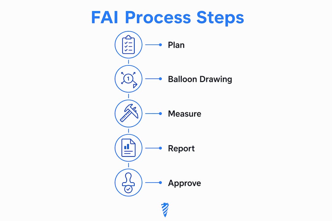
- How to perform an FAI from planning through approval
- Measurement equipment, calibration, and gauge R&R
- What to do when an FAI fails
- Common pitfalls and how to avoid them
- Expert insights: why FAIs fail and what the data shows
- Key Takeaways
- Balancing speed and defensible evidence in FAI
- Availzyemachinistpro cuts FAI paperwork without cutting corners
- Useful sources and templates
What a first article inspection actually validates
Most shops think of an FAI as a fancy incoming inspection. It is not. The point is to validate the process, not just the part sitting on the surface plate.

AS9102 defines the First Article Inspection Report (FAIR) using three forms, and every one of them is aimed at proving repeatability: Form 1 ties the part to a specific drawing and BOM revision, Form 2 captures material certifications and special-process approvals, and Form 3 records an actual measured value for every single drawing characteristic. Together they answer one question: if you run this job again tomorrow with the same machine, program, and tooling, will the part still conform?
Roles matter here. The supplier's QA team owns the FAIR package and is responsible for completing all three forms. The purchaser reviews and may witness the inspection, particularly on high-criticality aerospace or defense contracts. Third-party inspection labs step in when the supplier lacks the measurement capability or when the contract requires an independent witness. Knowing who signs what before the inspection starts prevents the last-minute scramble that derails more FAIs than bad parts do.
PPAP (Production Part Approval Process) is the automotive equivalent and shares the same philosophy, but the paperwork differs. PPAP typically requires additional elements such as process capability studies (Cpk), control plans, and a Process Failure Mode and Effects Analysis. FAI under AS9102 is the aerospace standard; PPAP is the automotive one. Some contracts require both.
When is an FAI required, and how long does it take?
The triggers are well-established across aerospace, defense, and precision manufacturing:
- New part number being produced for the first time
- Engineering change notice (ECN) that affects a drawing characteristic or material specification
- New tooling, fixture, or machine used to produce the part
- New supplier or production facility, even if the part number is unchanged
- Production restart after two or more years of inactivity
- Customer or contract requirement that explicitly calls for an FAI at defined intervals
The full vs. Delta decision comes down to scope. A full FAI covers every ballooned characteristic on the drawing. A Delta (partial) FAI covers only the characteristics affected by the change. If an ECN revises a single hole diameter and nothing else, a Delta FAI re-measures that feature and the surrounding characteristics that could be influenced by the change. If the part number changes, the tooling moves to a new machine, or the supplier changes, run a full FAI. No shortcuts.
Lead times vary significantly by part complexity. A simple turned part with 15 characteristics might take three to four hours of inspection time plus an afternoon of paperwork. A complex machined assembly with 200-plus characteristics, multiple special processes, and CMM programming can run three to five days. Budget for CMM setup and programming time, lab turnaround for material certifications, and the administrative time to assemble and route the FAIR package. The single biggest schedule killer is discovering mid-inspection that a material cert is missing or a gauge is out of calibration.
Pro Tip: Schedule the FAI planning meeting at the same time you release the first production order. Engineering, QA, and the shop floor all need to align on drawing revision, tooling IDs, and inspection equipment before the first chip falls.
Standards and paperwork: AS9102 Forms 1–3 and how FAI differs from PPAP
AS9102 is the governing standard for FAI in aerospace and has been widely adopted as best practice in defense, medical device, and other precision industries. The three-form structure is the backbone of every valid FAIR.
| Form | Primary Fields | Typically Completed By |
|---|---|---|
| Form 1: Part Number Accountability | Part number, drawing revision, BOM revision, design authority, FAI date, machine/tool IDs, program version | Supplier QA engineer |
| Form 2: Product Accountability | Material certifications, special-process approvals (plating, heat treat, anodize, weld), supplier certs | Supplier QA / process engineer |
| Form 3: Characteristic Accountability | Balloon number, characteristic description, nominal, tolerance, actual measured value, measurement method, equipment ID | Inspector / CMM operator |
Form 3 is where most FAIs fall apart. Inspectors record "PASS" next to a dimension instead of the actual measured value. That checkbox tells you nothing about process capability, nothing about how close the part is to the tolerance boundary, and nothing useful to a future auditor. Record actuals, always.
FAI vs. PPAP at a glance:
- FAI (AS9102) is the aerospace/defense standard; PPAP is the automotive standard (AIAG reference manual)
- PPAP typically requires a minimum of 300 pieces for capability studies (Cpk); FAI requires one production-intent part
- PPAP includes a control plan and PFMEA as required elements; AS9102 does not mandate them (though AS9100 QMS requirements may)
- Some contracts, particularly Tier 1 automotive suppliers doing aerospace work, require both
Pro Tip: Before submitting the FAIR, confirm that Form 1 references the exact drawing revision letter and BOM revision level currently on the shop floor. A FAIR signed against Rev B when production is running Rev C is invalid and will be rejected.
How to perform an FAI from planning through approval
Follow this sequence every time, regardless of part complexity.
-
Review the drawing and balloon every characteristic. Assign a unique balloon number to each dimension, tolerance, note, and surface finish callout. This is the foundation for Form 3. Ballooned drawings ensure 100% accountability and prevent characteristics from being overlooked. Export the balloon list to your inspection plan template.
-
Build the inspection plan. For each balloon number, specify the measurement method (CMM, micrometer, optical comparator, surface profilometer), the specific equipment ID, the calibration due date, and the acceptance criterion. The inspection plan is a living document; update it if measurement methods change during the inspection.
-
Produce the first article using production-intent everything. That means the actual production machine (not a setup machine), the released CNC program with the correct version number, the production fixture, the approved cutting tools with their tool IDs, and a qualified production operator. Record all of this on Form 1. If any of these elements differ from what will run in production, the FAI is not valid.
-
Measure every characteristic and record actual values. No pass/fail. No "OK." Write down 1.2487" or 0.0023" Ra. Use calibrated equipment and note the equipment ID and calibration date next to each measurement on Form 3. For borderline values, note the measurement uncertainty so auditors can interpret the result.
-
Assemble the FAIR package. Attach material certifications and special-process certifications to Form 2. Confirm that plating, heat treat, anodize, or weld certifications reference the correct specification and revision. Route the complete package for engineering and QA review and obtain all required signatures.
-
Disposition the FAI. If all characteristics conform, approve and release to production. If any characteristic fails, stop production, quarantine any parts already made, log the nonconformance, and initiate corrective action before re-measuring. Do not ship parts from a failed FAI run.
Compact pre-inspection readiness checklist:
- Drawing revision confirmed and ballooned
- Inspection plan complete with equipment IDs and calibration dates
- All gauges calibrated and within due date
- Production-intent tooling, fixture, and program confirmed
- Material certs and special-process certs in hand
- Reviewer sign-off fields identified and routed
Pro Tip: If your CAD system supports it, export the ballooned drawing directly to a spreadsheet or inspection software. Assigning balloon IDs in CAD and matching them to Form 3 rows eliminates transcription errors and cuts inspection-plan setup time significantly.
Measurement equipment, calibration, and gauge R&R
The measurement system has to be as trustworthy as the part. Here is how to choose equipment and document it correctly.
Common equipment and when to use it:
- CMM (Coordinate Measuring Machine): Best for complex geometry, true position, profile tolerances, and parts with many features. CMM programs are repeatable and reduce operator influence.
- Optical comparator / vision system: Efficient for 2D profiles, small features, and thread forms.
- Micrometer, caliper, bore gauge: Appropriate for simple linear dimensions where the tolerance is wide enough to make hand-tool uncertainty negligible.
- Surface profilometer: Required for Ra/Rz surface finish callouts. The surface finish calculator in Availzyemachinistpro can help you verify expected Ra values against cutting parameters before you measure.
- 3D scanner: Useful for freeform surfaces and castings where CMM point-by-point measurement would take too long.
Calibration traceability requirements for the FAIR:
Every piece of measurement equipment used in the FAI must have a current calibration certificate traceable to NIST. Record the equipment ID, calibration date, and calibration lab on Form 3 next to each measurement. If a gauge is out of calibration, stop and recalibrate before proceeding. Results from an out-of-calibration gauge are inadmissible.

Gauge R&R (Repeatability and Reproducibility) is a measurement system analysis that quantifies how much of your observed variation comes from the measurement process itself versus the part. For tight tolerances (under 0.001"), a formal gauge R&R study before the FAI is worth the time. The general threshold: if measurement system variation exceeds 30% of the tolerance, the measurement method needs to change before the FAI results mean anything. For most FAI characteristics, documenting measurement uncertainty alongside the actual value is sufficient.
What to do when an FAI fails
A failed FAI is not a crisis. It is the system working exactly as intended, catching a process problem before it ships to a customer.
Immediate steps:
- Quarantine the first article and any other parts produced during the same setup
- Place a production hold and notify engineering, QA, and the program manager
- Log the nonconformance with the specific balloon numbers that failed and the actual values recorded
Root-cause checklist:
- Check CNC program offsets and tool length compensation values
- Inspect fixture clamping and datum contact points for movement or wear
- Check insert/tool condition for wear or chipping
- Verify material certification matches the drawing specification
- Review the inspection method for the failed characteristic (wrong gauge, wrong datum reference)
- Confirm the correct drawing revision was used for setup
Corrective action flow: Containment → root cause analysis → corrective action implementation → verification run → re-measurement of all failed characteristics. Quality professionals recommend treating the failure as diagnostic: tool pathing errors, fixture offsets, and tool wear are the most common culprits, and each one points to a fixable upstream process issue.
Delta vs. full FAI after a failure: If the corrective action touches only the characteristics that failed and does not change the machine, tooling, or program structure, a Delta FAI covering those balloon numbers is sufficient. If the fix requires a new fixture, a different machine, or a revised CNC program that affects the overall setup, run a full FAI again. The Delta decision always comes back to scope: how many characteristics could the change have affected?
Common pitfalls and how to avoid them
The same mistakes show up in failed FAIs across industries. Most are avoidable.
Pitfall 1: Using non-production tooling or a setup machine. The FAI must reflect what production will actually use. Running the first article on a newer, more capable machine than the production machine invalidates the FAI for that production machine.
Pitfall 2: Recording pass/fail instead of actual values. This is the most common deficiency auditors cite. A checkbox tells you nothing about process margin. An actual value of 1.2499" on a 1.250" ±0.001" tolerance tells you the process is running close to the upper limit and needs attention.
Pitfall 3: Ballooning the wrong drawing revision. Always pull the drawing from the controlled document system immediately before ballooning. A drawing printed last week may already be superseded.
Pitfall 4: Missing or expired material certifications. Form 2 is incomplete without certs that reference the correct material specification and heat/lot number. Chase these before the inspection, not after.
Pitfall 5: Ignoring measurement capability. Using a 0–6" digital caliper to measure a 0.0005" tolerance feature is not a measurement; it is a guess. Match the equipment to the tolerance.
Best practices that prevent all of the above:
- Integrate FAI scheduling into the new-part launch checklist so it is never an afterthought
- Pre-verify all gauges the day before the inspection
- Include machine serial number, tool IDs, and program version on Form 1 before the part is cut
- Run a dry-run production setup with the QA inspector present to catch fixture and program issues early
- Store the approved FAIR in a controlled document system linked to the part number and drawing revision
Pro Tip: Build a standard FAI launch checklist into your new-part introduction (NPI) process. Every new job that hits the shop floor should automatically trigger an FAI planning task assigned to QA, with a due date tied to the first production run date.
Expert insights: why FAIs fail and what the data shows
Many shops incorrectly treat FAI as a single-part visual check. The actual requirement is broader: the FAIR must document the exact machine, tooling IDs, program versions, machine offsets, and operator used to produce the first article. Without that, you have validated a part, not a process. The distinction matters enormously when a customer auditor asks whether the 500th part off the line will look like the first.
Fixture clamping and tool wear are the two most common root causes of characteristic failures in machined parts. They are also the two causes most directly connected to shop maintenance practices. A worn insert that passes a visual check can still shift a critical diameter by 0.0008" over a 50-piece run. Integrating tool-life tracking with FAI planning, so that inserts are fresh for the first article run, eliminates a significant source of preventable failures.
A machined bracket with 42 ballooned characteristics initially failed 3 characteristics (7.1% characteristic failure rate); fixes were fixture clamping and worn insert, after rework the FAI passed. That example illustrates the real value of FAI. Catching them before production release prevented a potential field escape on every part in the run.
Quality experts are consistent on one point: pass/fail checklists are insufficient. Recorded actual values feed directly into SPC charts, capability studies, and future audits. An FAI that captures actuals becomes a process baseline you can compare against six months later to detect drift before it becomes a nonconformance.
Key Takeaways
A valid FAI requires production-intent tooling, actual measured values on Form 3, and complete material and process evidence on Form 2, all tied to the exact drawing revision on Form 1.
| Point | Details |
|---|---|
| Balloon the drawing first | Assign a unique number to every characteristic before building the inspection plan. |
| Record actual values, not pass/fail | Measured actuals enable capability analysis and make the FAIR defensible in future audits. |
| Match FAI scope to change scope | Use a Delta FAI for limited changes; run a full FAI when tooling, machine, or part number changes. |
| Document the process, not just the part | Form 1 must capture machine ID, tool IDs, program version, and operator for the FAI to validate a reproducible process. |
| Availzyemachinistpro for digital capture | The platform's Job Tracker and document management features log machine assignments, tool IDs, and program versions directly into the production record. |
Balancing speed and defensible evidence in FAI
The pressure to compress launch schedules is real, and FAI is almost always the item that gets squeezed. The argument goes: "We have a delivery date, the part looks good, let's ship and clean up the paperwork later." That logic has a predictable outcome. Paperwork assembled after the fact cannot prove what machine was used, which program version ran, or whether the material cert was on hand before production started. An auditor will see through it immediately.
The better approach is to treat FAI planning as part of the production planning cycle, not a quality add-on at the end. When engineering releases a new drawing, QA should be scheduling the inspection plan in the same week. When the first production order drops, the gauges should already be calibrated, the material certs should already be in the file, and the inspector should already know which balloon numbers are the critical ones.
Digital tools change the equation here. When machine IDs, tool IDs, and program versions are logged automatically in the production system, Form 1 practically fills itself. When material certs are attached to the job record at receiving, Form 2 is ready before the part is cut. The administrative overhead that makes FAI feel slow is mostly a paper-process problem, not an inspection problem.
Availzyemachinistpro cuts FAI paperwork without cutting corners
Assembling a FAIR manually, chasing material certs, transcribing CMM values into a spreadsheet, and routing paper forms for signatures can consume as much time as the inspection itself. Availzyemachinistpro is built to eliminate that overhead without sacrificing traceability.

The platform's G-Code Generator captures and stores the exact NC program version used for the first article run, giving you a direct link from Form 1 to the program file. The CAD Viewer supports STEP-to-STL import so you can work from the production drawing directly in the platform. The Tool Crib logs tool IDs and tool-life data, so the tooling record for Form 1 is already there when you need it. Document management handles material cert attachments for Form 2, and role-based access routes the FAIR to the right reviewers with a full audit log of who approved what and when.
Start a 7-day free trial at Availzye Machinist Pro and see how much of your FAI cycle time is paperwork you no longer have to do by hand.
Useful sources and templates
Use these references to implement FAI correctly and find templates your team can put to work immediately.
- AS9102 standard (SAE International): The governing aerospace FAI standard defining Forms 1–3 and the FAIR requirements. Purchase the current revision directly from SAE International at sae.org.
- AIAG PPAP manual (Automotive Industry Action Group): The automotive equivalent of FAI; required reading if your contracts reference PPAP levels. Available at aiag.org.
- AS9100 / ISO 9001: The QMS standards that provide the broader quality system context in which FAI results are stored and controlled. FAI can fulfill process validation requirements under both when documented correctly.
- OpenBOM FAI overview: A practical explanation of full vs. Delta FAI triggers and the requirement to record actual measured values.
- Engineering.com FAI guide: Covers lead-time expectations and corrective-action workflow for failed FAIs.
- Fabrico FAI guide: Explains ballooning practice, the process-validation scope of FAI, and the shop example cited in this article.
- Availzyemachinistpro reference docs: Document management and reference material storage for attaching material certificates and process documents to your FAIR package.
- Third-party metrology labs: For parts requiring CMM capability beyond what your shop has, labs accredited to ISO/IEC 17025 provide traceable measurement services and can serve as independent witnesses for high-criticality FAIs. Search the NIST NVLAP directory (nist.gov/nvlap) for accredited labs in your region.
This article is general informational guidance, not a substitute for the current AS9102 standard or professional quality engineering advice. Always verify requirements against the applicable contract, drawing, and standard revision for your specific program.