
G-code is the machine language that tells a CNC machine where to move, how fast, and what path to follow. Every CNC controller reads it as a series of instructions built from a small set of commands. If you're starting from zero, learn four things first: G00 (rapid move), G01 (straight-line cutting move), G02/G03 (circular arcs), and the fact that M-codes handle hardware like the spindle and coolant, not motion. Master those, and you can already read most simple programs.
TL;DR:
- Correctly using G00 and G01 is crucial to avoid machine crashes or damaging the part due to improper speed and position control.
- Understanding arc moves with G02 and G03 requires choosing between I/J/K offsets or R for radius, depending on the arc size and precision needed.
- Explicitly setting units with G20 or G21 and positioning mode with G90 or G91 at the start of each program prevents common location errors.
- Properly managing modal commands like G01 or G02, and verifying active modes before cutting, reduces mistakes caused by lingering settings.
- Always simulate and double-check offsets, tool numbers, and safe positions before actual cutting to prevent costly errors and ensure safety.
Table of Contents
- G-Code Structure: How to Read a Line
- Core Motion Commands: G00, G01, G02, and G03 Explained
- Setting Units and Positioning Mode: G20/G21 and G90/G91
- Coordinate Systems and Offsets: G53, G54 Through G59
- What Are Modal and Non-Modal Commands?
- How Do M-Codes Differ From G-Codes?
- Canned Cycles: Shortcuts for Drilling, Turning, and Threading
- Cutter Compensation and Tool Offsets: G40, G41, G42, and G43
- A Simple Annotated G-Code Program You Can Practice On
- Safety and Best Practices Every Beginner Should Follow
- Why the Fundamentals Matter More Than the Fancy Features
- Practice G-Code Faster With the Right Tools
- Where to Learn More About G-Code
- Sources
G-Code Structure: How to Read a Line
A G-code program is a stack of instructions called blocks. Each block is one line, and each block is made of words. A word is just a letter paired with a number, like X1.5 or F100. String a few words together and you have a complete instruction: G01 X1.5 Y0.5 F10.0 tells the machine to cut a straight line to that X/Y position at a feed rate of 10 units per minute.
Some blocks start with an N number (N010, N020). These are optional sequence numbers, mostly there for human readability or as restart points after a stopped job. The controller doesn't care about them. It executes the file top to bottom regardless of what number sits at the front of the line, so don't rely on N-numbers to control order, and don't overload your file with them just to look organized. A LinuxCNC overview of program structure breaks this down clearly if you want the formal reference.
Address letters are the alphabet of G-code. Learn these and you can decode nearly any block:
- G: motion type or preparatory function (rapid move, linear cut, arc, canned cycle)
- M: miscellaneous machine function (spindle on/off, coolant, program end)
- X, Y, Z: linear axis positions
- I, J, K: arc center offsets relative to the start point (paired with X, Y, Z respectively)
- F: feed rate, the speed of a cutting move
- S: spindle speed, usually in RPM
- T: tool number to select
- D: cutter diameter offset number
- H: tool length offset number
Comments live inside parentheses, like (finish pass), and the controller skips over them entirely. Some dialects use a semicolon instead. Either way, comments are for you, not the machine, and a well-commented file saves you real time when you come back to edit it six months later.
Core Motion Commands: G00, G01, G02, and G03 Explained
These four codes handle nearly every physical move a CNC machine makes. Everything else in G-code programming is really just supporting these commands with context.
G00 is rapid positioning. The machine moves at its maximum non-cutting travel speed, in a straight line or sometimes a dogleg path depending on the controller. You use it to get the tool from point A to point B fast when it isn't touching material.
G00 X0 Y0 Z1.0
That block sends the tool rapidly to X0, Y0, at a height of 1 inch or millimeter above the part. Never use G00 while the tool is in the material. It doesn't respect a feed rate, and that's exactly the problem: a G00 move plows through space at full speed, and if there's a clamp, a vise jaw, or the part itself in the way, something breaks.
G01 is linear interpolation, the cutting workhorse. It moves the tool in a straight line at a controlled speed set by the F word.
G01 X2.0 Y0.5 F8.0
G01 requires a programmed feed rate to function — if F was never set earlier in the program, most controllers will either throw an alarm or, worse, run at whatever leftover feed rate was active, which may not be what you intended.
G02 and G03 cut arcs, clockwise and counterclockwise respectively, viewed from the positive tool axis looking down. You define the arc two ways: with I/J/K offsets (the distance from the start point to the arc center) or with an R value (the radius directly).
G02 X1.0 Y1.0 I0.5 J0 F6.0
G03 X1.0 Y1.0 R0.5 F6.0
The I/J/K method is more precise for arcs greater than 180 degrees, since a radius value alone can be ambiguous about which of two possible arcs you mean. R notation is quicker to write and read for simple, small arcs.
- Identify whether the move is rapid (no cutting) or a cutting pass — that decides G00 versus G01.
- Confirm a feed rate is active before any G01, G02, or G03 block runs.
- For arcs, decide between I/J/K and R based on arc size and whether ambiguity is a risk.
Pro Tip: Always run a new or edited program in simulation before cutting metal. A single missed decimal point in an I or J value can send an arc move somewhere the fixture never expected — better the software catches it than the spindle.
Setting Units and Positioning Mode: G20/G21 and G90/G91
Two mode decisions sit at the top of nearly every G-code file, and getting either one wrong is one of the most common ways beginners crash a machine or ruin a part.
G20 sets the machine to work in inches. G21 sets it to millimeters. Neither is a default you should assume is already correct. Machines remember whatever mode was active last, which means a program written in millimeters run on a machine still sitting in inch mode will move everything at roughly 25 times the intended distance. Setting units explicitly at the top of every program removes that guesswork entirely.
G90 is absolute positioning: every coordinate refers back to a fixed zero point, so X1.0 always means "go to X equals 1," regardless of where the tool currently sits. G91 is incremental positioning: every coordinate is relative to the tool's current position, so X1.0 means "move 1 unit further in X from wherever you are right now."
- Use G90 for most programs, since absolute coordinates are easier to read, debug, and verify against a drawing.
- Use G91 for repeating patterns, like a bolt-circle of holes spaced evenly apart, where relative steps are simpler to write.
- Mixing them without noticing is a classic beginner error, since a block that looks correct in G90 can send the tool somewhere completely different in G91.
Feed rate and spindle speed values correspond to the selected units: under G20 (inches), feed rate is interpreted in inches per minute; under G21 (millimeters), feed rate is interpreted in millimeters per minute.
Coordinate Systems and Offsets: G53, G54 Through G59
CNC machines actually track two separate coordinate systems at once, and understanding the difference between them prevents one of the more dangerous mistakes a beginner can make.
G53 moves the tool in the machine coordinate system, the fixed reference tied to the machine's physical limit switches and home position. It ignores every work offset currently active. Shops use it mainly for safe retract positions, like sending the tool to a tool-change location that's always the same regardless of what part or fixture is loaded.
G54 through G59 are work offsets, each one storing a separate zero point tied to wherever the operator actually clamped the part on the table. This is what lets the same program run against different vises or fixtures without rewriting a single coordinate. Program the part relative to G54, and if a second vise sits somewhere else on the table, you simply call G55 and adjust that offset instead of touching the code.
- Offsets get set either by touching off manually at the control panel or by writing them programmatically with G10 (useful for probing routines or automated setups).
- A common shop workflow: two vises on the table, part one uses G54, part two uses G55, and the same G-code file runs against both by changing only which offset the operator calls.
- Always verify an offset with a quick jog to a known feature before the first cut. A wrong offset value sends the tool to the wrong zero point, and the G-code fundamentals guide from UTEC is a solid reference for how coordinate systems interact with modal state.
What Are Modal and Non-Modal Commands?
A modal command stays active until something else in the same category replaces it. Call G01 once, and every following block that only has coordinate words (X1.0 Y2.0) keeps cutting in a straight line at whatever feed rate was last set, with no need to repeat G01 every time.
A non-modal command fires once and doesn't persist. G04 (dwell, a pause for a set duration) is a good example: it executes for that one block and has no lasting effect on the next line.
G-codes are generally modal while M-codes are typically non-modal, one-shot instructions, which is part of why the two code families exist separately in the first place.
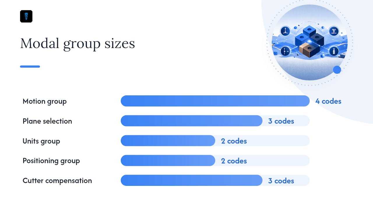
Modal codes are organized into modal groups, and only one member of a group can be active at a time:
- Motion group: G00, G01, G02, G03 (only one governs the current move type)
- Plane selection group: G17, G18, G19 (which two axes define the arc plane)
- Units group: G20, G21
- Positioning group: G90, G91
- Cutter compensation group: G40, G41, G42
Calling a new member of a group automatically cancels whatever was active in that same group before it. This is a frequent source of beginner errors: forgetting that switching from G02 to G01 silently ends the arc mode, or assuming G20 is still active hours after someone else's program left the machine in G21. Reading the control panel's active modal display before running any file tells you exactly what state the machine thinks it's in.
Pro Tip: Trainers commonly recommend explicitly setting units and positioning mode at the start of every program, even when you're confident the machine is already in the right state — it costs one line and removes an entire category of mistakes, a point echoed in LinuxCNC's own modal group documentation.
How Do M-Codes Differ From G-Codes?
G-codes handle motion and geometry. M-codes handle everything else the machine's hardware needs to do: spindle direction, coolant flow, program stops. That split matters because forgetting an M-code doesn't usually throw an error, it just means the hardware never turns on, and you find out when the tool touches a part that isn't spinning.
- M03: spindle on, clockwise
- M04: spindle on, counterclockwise
- M05: spindle stop
- M08 / M09: coolant on/off (varies by machine)
- M06: execute a tool change
- M30: program end and reset to the top of the file
F sets feed rate and applies to cutting moves like G01, G02, and G03. S sets spindle speed in RPM and usually pairs with M03 or M04. T selects a tool number, typically written alongside M06 as in T02 M06. Place F and S words on or before the line that needs them, since both are modal and stay active until changed.
Canned Cycles: Shortcuts for Drilling, Turning, and Threading
Canned cycles are pre-built routines that replace what would otherwise take several blocks of explicit moves. Drilling a hole with G01 alone means programming the plunge, the retract, and the repeat for every single hole. A canned cycle compresses that into one line.
- G81: basic drilling cycle, rapid to the hole, feed down to depth, rapid retract
- G80: cancels any active canned cycle, always call it when you're done drilling
- G71: rough turning cycle on lathes, removes material in a series of passes toward a finished profile
- G76: threading cycle, handles the repeated passes needed to cut a thread to depth
Canned cycles shorten programs dramatically. A pattern of twenty holes might take twenty lines with a cycle active instead of a hundred lines of explicit G01 moves. The tradeoff is readability for someone unfamiliar with the specific cycle's parameters, so CAM-generated code that uses them heavily is worth running through simulation first rather than editing live. For one-off moves or unusual geometry, explicit G01/G02/G03 blocks are still often clearer to write and debug.
Cutter Compensation and Tool Offsets: G40, G41, G42, and G43
Cutter compensation exists so you can program the actual part geometry, the line a drawing shows, without recalculating every coordinate for the specific tool diameter in the spindle. G41 applies compensation to the left of the programmed path, G42 applies it to the right, and G40 cancels compensation entirely.
- G41 / G42: shift the tool path by half the tool diameter, left or right of the line you actually programmed
- G43: applies tool length offset, paired with an H number that stores how long that specific tool is
- Always confirm the D (diameter) and H (length) offset numbers loaded match the physical tool in the spindle before the first cut
A mismatched offset is one of the most common causes of a ruined part or a broken tool, since the machine will faithfully cut exactly where the wrong numbers tell it to. A tool crib system that tracks which offset belongs to which physical tool removes a lot of that guesswork on a busy shop floor.
Pro Tip: Before running any program with cutter compensation active, jog the tool to a known reference point and verify the displayed position matches. It takes thirty seconds and catches an offset error before it costs you a part.
A Simple Annotated G-Code Program You Can Practice On
Here's a short program that touches the fundamentals covered so far. Run it only in simulation until you're comfortable with every line.
G21 G90 G17
G54
G00 Z1.0
M03 S1200
G00 X0 Y0
G01 Z-0.5 F5.0
G01 X2.0 F10.0
G02 X2.0 Y2.0 I0 J1.0 F8.0
G01 X0 F10.0
G00 Z1.0
M05
M30
G21 G90 G17sets millimeters, absolute positioning, and the XY arc plane, all in one line.G54calls the first work offset, so every coordinate that follows is relative to that fixture's zero.G00 Z1.0rapids up to a safe height before anything else happens.M03 S1200starts the spindle clockwise at 1,200 RPM.G00 X0 Y0rapids over the starting position, still above the part.G01 Z-0.5 F5.0plunges into the material at a controlled feed rate.G01 X2.0 F10.0cuts a straight line.G02 X2.0 Y2.0 I0 J1.0 F8.0cuts a clockwise arc.G01 X0 F10.0cuts back toward the start.G00 Z1.0retracts to a safe height,M05stops the spindle, andM30ends the program.
Before running anything like this against real material, beginner-focused references recommend a simulation pass first, then a single-block run at reduced feed and spindle speed, confirming the offset and tool number on screen matches what's actually loaded.
Safety and Best Practices Every Beginner Should Follow
A few habits catch the vast majority of beginner mistakes before they become expensive ones.
- Run a full simulation or dry run with the Z-axis lifted clear of the part before the first real cut.
- Use single-block mode for the first pass through any new or edited program.
- Cut the feed rate and spindle speed override down for that first run, then bring them back up once you've confirmed the path looks right.
- Double-check the active work offset and tool number against what's physically loaded in the machine.
- Watch for a units mismatch (G20 versus G21) and a positioning mismatch (G90 versus G91), the two most common causes of a program moving somewhere unexpected.
Pro Tip: If a move looks wrong on the first single-block step, hit feed hold immediately and check the modal display before advancing to the next block. It's far easier to diagnose a problem with the machine paused than after it's already cut into something it shouldn't have.
Why the Fundamentals Matter More Than the Fancy Features
Most people rushing into CNC work want to skip straight to macros, probing routines, and multi-axis toolpaths. That instinct is backwards. A shop that has its people fluent in G00, G01, G02/G03, offsets, and modal state moves faster on every job, not just the simple ones, because nobody's stopping mid-run to figure out why a move went sideways.
The small checks, confirming an offset, running single-block on a new program, reading the modal state before hitting cycle start, take seconds. Skipping them costs hours of rework or a broken tool. A focused set of about ten G-codes covers the overwhelming majority of what a beginner needs to be productive on real parts. Learn those cold before chasing anything more advanced, and practice in simulation until reading a block feels automatic rather than a translation exercise.
— Availzye
Practice G-Code Faster With the Right Tools
Reading G-code by hand builds real skill, but nobody wants to hand-write every arc offset or double-check a canned cycle's syntax under a deadline. Availzyemachinistpro's G-code generator builds and checks programs for you, catching the kind of unit mismatches and modal errors that trip up beginners long before they reach the machine.

The platform also includes a G-code wizard for walking through cycles step by step, plus feeds-and-speeds and tool offset calculators that pair directly with the F and S words covered in this guide. Instead of guessing at a feed rate or rebuilding an offset table from scratch, you get the numbers already checked against the tool and material. Start a free trial and run your next program through it before it ever reaches the spindle.
Where to Learn More About G-Code
A few sources go deeper than this guide if you want formal or supplementary reading. The LinuxCNC G-code overview documents modal groups and program structure in full technical detail. HowToMechatronics' G-code command list is a handy quick reference for motion commands. UTEC's G-code fundamentals guide covers coordinate systems and dialect differences well, and Bantam Tools' G-code introduction offers a beginner-friendly example program with safety notes. For background on how the G-code standard itself developed, Wikipedia's entry on RS-274 and ISO 6983 is a useful starting point.
Sources
- G-code Explained | List of Most Important G-code Commands
- CNC G-code basics — Zappettini Consulting
- G-code overview — LinuxCNC
- G-Code fundamentals: program structure, coordinates, and modal commands — UTEC
- G-code introduction — Bantam Tools support