
For most precision shaft/hole assemblies, use a hole-basis fit with ISO 286 designations — H7/p6 for a light press fit, H7/s6 for a driving fit, or H7/u6 for a forced fit — then verify with vendor bore tolerances, material properties, and a worked interference calculation before committing to production.
Before you touch a tolerance table, run through this checklist:
- Consult ISO 286 for the letter/grade system and numeric deviation tables.
- Cross-reference ANSI B4.2 for inch-unit practice and US shop conventions.
- Pull the relevant section from Machinery's Handbook for worked examples and material-specific guidance.
- Request the vendor's actual bore tolerance and first-article inspection data — do not assume the standard fits will match every supplier's process.
- Run a quick interference calculation (D_shaft − D_hole) and estimate assembly force before finalizing the fit class.
Table of Contents
- What do clearance, transition, and interference fits actually mean?
- How do ISO 286 and ANSI B4.2 tolerance tables work?
- Hole-basis vs shaft-basis: which system should you use?
- How do you calculate interference and estimate press force?
- How do material properties and surface finish change your tolerance choice?
- What assembly method should you use, and what do you inspect afterward?
- How do you verify vendor tolerances before production?
- Using Availzyemachinistpro to compute interference and evaluate assembly options
- What safety factors and design margins should you apply?
- How do temperature, corrosion, and lubrication affect press-fit performance?
- Key Takeaways
- The part of press-fit design most engineers get wrong
- Availzyemachinistpro cuts press-fit iteration time from days to minutes
- Primary standards and references
What do clearance, transition, and interference fits actually mean?
The fit type you choose determines whether parts slide, locate, or lock together permanently. Getting this wrong at the design stage means either a sloppy assembly that walks under load or a cracked housing on the press.
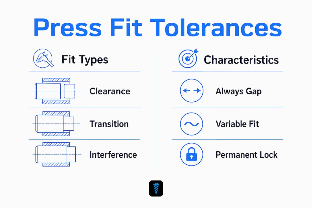
Clearance fits guarantee a gap between shaft and hole at all tolerance extremes. The shaft is always smaller than the bore, so parts slide or rotate freely. Journal bearings, sliding bushings, and spindle bores are the classic applications. A designation like H7/g6 produces a small, controlled clearance — tight enough for accurate location but loose enough to assemble by hand.
Transition fits sit in the gray zone: depending on where actual dimensions land within their tolerance bands, you might get a slight clearance or a slight interference. Locating dowel pins and precision-located flanges often use transition fits because they need accurate positioning without requiring a press. H7/k6 and H7/n6 are common examples.
Interference fits (press fits) guarantee the shaft is always larger than the bore. The material deforms elastically on assembly, generating the contact pressure that creates torque and axial retention. Pressed-in bushings, gear hubs on shafts, and bearing outer rings in housings are the standard use cases. H7/p6 is a light press fit; H7/s6 and H7/u6 step up to driving and forced fits with progressively higher interference.
A few shop realities worth keeping in mind:
- Clearance fits are reversible; interference fits generally are not without damage.
- Interference fits transfer torque and axial load through friction alone — no key, no fastener.
- Transition fits can be disassembled with a soft mallet; interference fits need a press or thermal method.
- The heavier the interference, the more critical material hardness and surface finish become.
Pro Tip: If you are unsure whether a locating feature needs a transition or light press fit, ask yourself whether the part must ever be serviced. If yes, a transition fit (H7/k6 or H7/m6) is far easier to disassemble than even a light H7/p6.
How do ISO 286 and ANSI B4.2 tolerance tables work?
The letter in a fit designation tells you the position of the tolerance band relative to the nominal size; the number tells you how wide that band is.
For the hole, uppercase letters set the fundamental deviation. "H" means the lower deviation is zero — the hole is always at or above nominal. For the shaft, lowercase letters set the deviation. "p" means the shaft's lower deviation is above zero (the shaft is always larger than nominal), which is why H7/p6 produces interference.
The number is the IT grade (International Tolerance grade). IT grades run from IT01 (tightest) through IT16 (loosest). IT5–IT7 covers precision fits for general engineering. IT8–IT11 handles general-purpose work. The tolerance band width grows with both IT grade and nominal diameter, which is why a ⌀50 mm H7 hole has a wider absolute tolerance than a ⌀10 mm H7 hole, even though both are "H7."
Worked numeric example: H7/p6 at ⌀20 mm nominal
| Parameter | Hole (H7) | Shaft (p6) |
|---|---|---|
| Nominal diameter | 20 mm | 20 mm |
| Fundamental deviation | 0 µm (lower) | +35 µm (max) |
| IT grade tolerance | +21 µm (IT7) | — |
| Upper limit | approximately 0.001 mm (1 µm) | +0.035 mm (35 µm) |
| Lower limit | 0 µm → 20 mm | — |
Minimum interference = shaft lower limit − hole upper limit, producing a very small positive interference suitable for a light press fit
Maximum interference = shaft upper limit − hole lower limit, resulting in a modest interference range typical for a light press fit
Converting to inches, the interference range corresponds to a very small value appropriate for light press fits. That is a light press fit — achievable with a small arbor press and light lubrication.
For ANSI B4.2 inch practice, the same letter/grade logic applies but tables are organized by nominal size ranges in inches. Published interference fit charts list light, medium, and heavy press interference bands by size range, which gives you a fast sanity check against your calculated values.
Pro Tip: Machinery's Handbook carries complete ISO 286 and ANSI B4.2 tables with worked examples. It is the single most reliable shop-floor reference for converting fit designations into numeric limits, and it covers both metric and inch systems in one place. The tolerance calculator in Availzyemachinistpro handles the same conversion interactively.
Hole-basis vs shaft-basis: which system should you use?
Hole-basis is the default for most new designs because holes are produced by drilling and reaming — processes that are hard to adjust after the fact. Shafts, by contrast, are easy to resize by turning or grinding. Fixing the hole deviation at zero (H) and varying the shaft letter to achieve the desired fit class is simply more practical and cheaper to manufacture.
Use hole-basis unless one of these conditions applies:
- Purchased components control the shaft size. If you are fitting a bearing onto a standard ground shaft, the shaft OD is fixed and you size the housing bore to match — that is shaft-basis.
- A pre-existing shaft cannot be reworked. Repair situations where the shaft is already in service and cannot be reground.
- Supplier tooling is optimized for a specific shaft diameter. Some high-volume suppliers hold tighter shaft tolerances than bore tolerances, making shaft-basis cheaper at scale.
- Multiple components share one shaft. When several bores of different fit classes must mate with the same shaft diameter, shaft-basis avoids the need for multiple shaft diameters.
For new designs with standard tooling and no pre-existing constraints, hole-basis with H7 as the bore designation covers the vast majority of press-fit applications. Change the shaft letter (g6, k6, p6, s6, u6) to move from clearance through transition to heavy interference.
How do you calculate interference and estimate press force?
The core formula is straightforward. Interference = D_shaft − D_hole, calculated at both the min and max tolerance extremes to bracket the assembly condition.

Once you have the interference value, contact pressure P comes from a Lamé-based relation for thick-walled cylinders. For a solid shaft pressed into a housing:
P = (δ / D) × [E_shaft × E_housing / (E_shaft + E_housing)]
where δ is the diametral interference, D is the nominal diameter, and E values are Young's moduli for each material. For a steel-on-steel pair, this simplifies considerably. Assembly force then follows:
F = μ × P × π × D × L
where μ is the friction coefficient between the mating surfaces, and L is the contact length.
Step-by-step for the ⌀20 mm H7/p6 example (steel shaft, steel housing)
- Minimum interference: 0.001 mm (1 µm) — from the table above.
- Maximum interference: 0.035 mm (35 µm).
- Contact pressure at max interference: Using E = 200 GPa for both parts and δ/D = 0.035/20 = 0.00175, P ≈ 175 MPa. This is well within yield for most carbon steels.
- Assembly force at max interference: Assuming typical friction and contact length values, the resulting assembly force is within the capacity of a small hydraulic press.
- Assembly force at minimum interference: Proportionally lower — roughly 75 N. This is why minimum interference matters: too little and the joint slips under load.
Pro Tip: Keep units consistent throughout. Mix mm and MPa, and the formula works directly. Switch to inches and psi if your shop runs ANSI tables — but never mix the two in the same calculation. For thin-walled housings where wall thickness is less than roughly twice the bearing OD, simple Lamé formulas underestimate hoop stress and you need FEA or published correction factors.
How do material properties and surface finish change your tolerance choice?
Material choice is not a secondary concern — it sets the ceiling on how much interference you can safely specify.
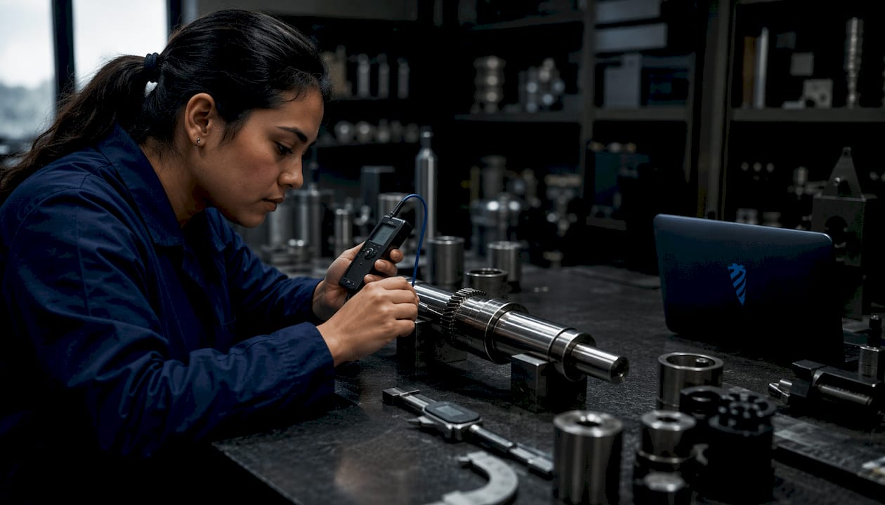
Harder materials tolerate less deformation before cracking. A steel shaft pressed into a gray cast iron housing needs tighter interference limits than the same shaft into a ductile steel housing, because cast iron has almost no ductility to absorb hoop stress. Aluminum housings expand more under contact pressure and have a lower modulus, so the effective interference at operating temperature may differ significantly from what you measured cold on the bench.
Practical material notes:
- Steel on steel: Standard interference ranges apply; surface finish is the main variable.
- Steel shaft in aluminum housing: Reduce interference by roughly 20–30% to account for aluminum's lower modulus and higher thermal expansion. Confirm with calculation.
- Bronze bushings: Softer and more forgiving, but galling risk increases if surface finish is poor.
- Plastics and composites: Interference fits are possible but require very small interference values and careful attention to creep under sustained load.
Surface finish has a direct effect on retention. The recommended Ra range for metal-on-metal press fits is 0.8–3.2 µm. Surfaces rougher than 6.3 µm lose effective interference because the peaks smear during pressing rather than generating uniform contact pressure. Counterintuitively, surfaces that are too smooth (below ~0.4 µm Ra) can micro-weld under high contact pressure, making disassembly destructive even for fits that were designed to be serviceable.
Use the surface finish calculator to verify Ra targets before sending parts to the grinder or hone.
Coatings and platings add real thickness. A 25 µm hard chrome layer on a shaft OD effectively increases the shaft diameter by 25 µm per side — which can flip a transition fit into a heavy interference fit. Always specify coating thickness as part of the finished dimension, not as an afterthought.
Pro Tip: When specifying a plated or coated shaft, call out the finished OD after coating on the drawing, not the pre-plate diameter. Shops that plate to a nominal thickness range can easily add 10–50 µm of variation that your tolerance stack never accounted for.
What assembly method should you use, and what do you inspect afterward?
The fit class and interference magnitude drive the assembly method choice. Getting this wrong damages parts that are otherwise within tolerance.
Assembly methods by fit class
- Manual arbor press: Suitable for light press fits (H7/p6 at small diameters, typically under ⌀25 mm). Controllable, low cost, but offers no force monitoring.
- Hydraulic press: The standard for medium to heavy interference fits. Allows force monitoring throughout the stroke — a spike in force mid-stroke signals misalignment or a surface defect.
- Thermal (shrink-fit) assembly: Heat the housing to expand the bore, or chill the shaft (dry ice or liquid nitrogen) to shrink it, then assemble with zero pressing force. Preferred for heavy interference fits, fragile housings, or when pressing would damage rolling elements. Typical temperature differentials are 100–200°C for most steel assemblies.
- Hydraulic expansion: Used for large-diameter or long-contact-length fits where press force would be impractical.
- Adhesive-assisted: Retaining compounds (e.g., anaerobic adhesives) can supplement a light interference fit or substitute for press fits in low-load applications. Not a replacement for a properly sized interference fit under significant torque or axial load.
Inspection checklist after assembly
- Verify runout on the assembled shaft or bore with a dial indicator; a skewed press-in shows up immediately.
- Check for visible scoring, galling, or material pickup on the shaft OD or bore ID — these indicate surface finish or alignment problems.
- Perform axial push-out or torque retention testing on sample assemblies to confirm the joint meets load requirements.
- Measure any post-assembly dimensional changes on thin-walled housings (bore growth after pressing is common and expected; excessive growth signals over-interference).
- Document press force vs. displacement curves for each production assembly when using a hydraulic press. A consistent force curve is the best real-time QA signal you have.
Lead-in chamfers of 15°–30° on both the shaft end and bore entry are not optional for production runs. They center the parts before engagement, reduce scoring risk, and make force curves smoother and more repeatable.
Pro Tip: Run a trial assembly on the first article and instrument the press with a load cell. Document the force curve. If production parts later show force spikes outside that baseline range, stop and investigate before scrapping a batch.
How do you verify vendor tolerances before production?
Standards tell you what the tolerance should be. Vendors tell you what they actually made. Those two numbers are not always the same, and a planned transition fit can become a clearance or interference fit if the vendor's process drifts.
Before locking a fit for production, require the following from your supplier:
- Actual bore or shaft dimensions from first-article inspection (not just "conforms to drawing").
- Process capability data (Cpk or Cp) for the critical diameter, especially for high-volume runs.
- Heat treatment certification and hardness results when hardness affects interference behavior.
- Coating or plating thickness range, not just a nominal value.
- Surface finish measurement (Ra) on the mating surfaces.
On the shop floor, your verification steps are:
- First-article inspection: Measure every critical dimension on the first part off the machine. CMM or a calibrated bore gauge for the hole; a micrometer or air gauge for the shaft.
- Go/no-go gauges: Fast, reliable, and shop-proven for production sampling. Set them to the drawing limits, not the nominal.
- Sample CMM checks: For tight-tolerance fits (IT6 and finer), periodic CMM verification catches drift that go/no-go gauges miss.
If parts arrive out of spec, you have four options: redesign the fit to accommodate the actual vendor spread, request rework, qualify a different supplier, or switch assembly method (thermal assembly is more forgiving of dimensional variation than pressing).
Pro Tip: Build vendor bore tolerance into your interference calculation from day one. If the vendor holds ±0.010 mm on a bore that your design assumes ±0.005 mm, your minimum interference may disappear entirely. Ask for the Cpk before you finalize the fit class, not after the first production run.
Using Availzyemachinistpro to compute interference and evaluate assembly options
Running the calculation manually is straightforward for a simple steel-on-steel pair. For anything more complex — mixed materials, coatings, thin walls, or multiple fit classes on one assembly — a structured calculator workflow saves time and reduces transcription errors.
Here is the workflow using Availzyemachinistpro's tolerance calculator:
- Enter the nominal diameter. For the ⌀20 mm example, type 20 mm.
- Select the fit designation. Choose H7 for the hole and p6 for the shaft from the dropdown. The calculator returns the upper and lower limits for both parts.
- Read min/max interference directly. The output matches the manual calculation: 1 µm minimum, 35 µm maximum for H7/p6 at ⌀20 mm.
- Enter material properties. Select steel for both parts, or pull values from the material database for Young's modulus and Poisson's ratio.
- Enter contact length and friction coefficient. The calculator returns estimated contact pressure and assembly force range.
- Log the result. Use the Job Tracker to attach the calculation to the work order, so the shop floor has the expected press force range before the first part goes under the press.
The AI Assistant can flag when your interference-to-wall-thickness ratio suggests FEA is warranted, or when the specified Ra is outside the recommended range for the material pair. That kind of check used to require a senior engineer reviewing the drawing — now it happens before the drawing leaves the design office.
Pro Tip: After the first-article assembly, update the Job Tracker with the actual press force curve data. If the production run later shows drift, you have a documented baseline to compare against rather than relying on memory.
What safety factors and design margins should you apply?
A calculated interference value is a theoretical number. Real assemblies have dimensional variation, surface finish variation, and load conditions that are rarely perfectly characterized at design time. Safety factors translate that uncertainty into a margin you can defend.
For static torque and axial retention, a safety factor of 1.5–2.0 on the minimum interference is common in general engineering practice. That means your minimum interference (worst-case tolerance stack) should still generate enough contact pressure to carry 1.5–2.0 times the maximum expected load. For dynamic or shock loads, push that margin to 2.5–3.0.
A few specific situations where the standard margin is not enough:
- Brittle materials (cast iron, hardened steel, ceramics): The failure mode is sudden cracking, not gradual slip. Reduce maximum interference to stay well below the hoop-stress limit, and verify with a stress calculation or FEA.
- High-cycle fatigue loading: Fretting corrosion at the interface degrades retention over time. Increase interference to maintain contact pressure as fretting wear progresses, or apply a surface treatment (phosphate coating, molybdenum disulfide) to reduce fretting damage.
- Temperature cycling: If the assembly sees wide temperature swings, calculate interference at both the cold and hot extremes. A fit that is adequate at room temperature may go slack at operating temperature if the housing material has a higher thermal expansion coefficient than the shaft.
- Thin-walled housings: As noted earlier, wall thickness below roughly twice the bore diameter requires correction factors or FEA. The simple Lamé formula overestimates contact pressure in this geometry.
Document your safety factor choice on the drawing or in the design record. If a failure investigation ever asks why you chose a particular interference range, "we applied a 2.0 safety factor on minimum interference per our design standard" is a defensible answer.
How do temperature, corrosion, and lubrication affect press-fit performance?
Environmental conditions can quietly erode a press fit that looked perfectly adequate on paper.
Temperature variation is the most common culprit in US industrial contexts. Steel and aluminum have different coefficients of thermal expansion — roughly 12 µm/m·°C for steel versus 23 µm/m·°C for aluminum. A steel shaft in an aluminum housing that starts with 30 µm of interference at room temperature loses interference as temperature rises, because the aluminum housing expands faster than the steel shaft. At 150°C above assembly temperature, that 30 µm can drop to near zero for a ⌀20 mm assembly. Calculate the interference at the maximum operating temperature, not just at assembly.
Corrosion attacks the contact interface in two ways. General corrosion (rust, oxidation) builds up oxide layers that effectively increase the shaft diameter over time, potentially locking a serviceable fit permanently. Fretting corrosion — the micro-slip wear that occurs at press-fit interfaces under vibration — generates fine oxide debris that reduces contact area and retention force. In wet or corrosive environments, specify corrosion-resistant materials or apply a protective coating to the mating surfaces before assembly.
Lubrication during assembly reduces press force and surface damage, but it also reduces the friction coefficient at the interface. If your retention calculation assumes a dry steel-on-steel friction coefficient of 0.15–0.20, but you assemble with oil (μ ≈ 0.10–0.12), your actual retention force is lower than calculated. Either recalculate with the lubricated friction coefficient, or specify that the joint must be assembled dry after a cleaning step.
Press-fit plumbing components — like stainless steel press-fit ball valves used in fluid-handling systems — face all three of these environmental factors simultaneously, which is why their interference specifications are tighter and their material choices more deliberate than general mechanical assemblies.
Key Takeaways
Reliable press fits come from combining the right fit designation with verified vendor dimensions, correct material and surface finish choices, and a documented assembly process.
| Point | Details |
|---|---|
| Start with hole-basis H7 | Use H7/p6 for light press, H7/s6 for driving, H7/u6 for forced fits; verify against ISO 286 and ANSI B4.2. |
| Calculate min and max interference | Interference = D_shaft − D_hole at both tolerance extremes; minimum interference must carry your safety factor load. |
| Match surface finish to the fit | Target Ra 0.8–3.2 µm for metal-on-metal press fits; surfaces rougher than 6.3 µm reduce effective retention. |
| Verify vendor tolerances before production | Request actual Cpk data and first-article inspection reports; do not assume standard fits match every supplier's process. |
| Availzyemachinistpro speeds the workflow | The tolerance calculator, material database, and Job Tracker let you compute interference, log assembly results, and track tooling in one platform. |
The part of press-fit design most engineers get wrong
The standards are not the hard part. ISO 286 is well-documented, ANSI B4.2 is accessible, and Machinery's Handbook walks you through the arithmetic. What actually causes press-fit failures in production is the gap between the calculated fit and the assembled reality.
The most common failure pattern: a designer specifies H7/p6, the drawing goes to a vendor, the vendor holds the bore to ±0.015 mm instead of the ±0.010 mm the H7 grade implies, and the minimum interference disappears. The assembly passes visual inspection, goes into service, and the bushing walks out under load three months later. Nobody connects the failure to the vendor's bore tolerance because nobody checked it before production.
The second most common failure is surface finish. Engineers specify the fit class correctly but leave surface finish as "125 µin Ra" (about 3.2 µm) on the drawing without checking whether the vendor's turning process actually hits that number on the bore. A bored hole that comes in at 5–6 µm Ra loses a meaningful fraction of its retention capacity, and that loss is invisible until the joint slips.
A few things that actually work in practice: require first-article CMM data on every new vendor relationship, not just a certificate of conformance. Run a trial assembly with a load cell before committing to a production run. And when a press-fit joint fails in the field, measure the actual parts before you redesign the tolerance — more often than not, the design was fine and the process was the problem.
Availzyemachinistpro cuts press-fit iteration time from days to minutes
Every interference calculation you run manually is one you have to redo when the vendor changes their process or the material substitution comes in. Availzyemachinistpro's tolerance calculator handles the full H7/p6 workflow interactively: enter nominal diameter, select fit class, choose materials, and get min/max interference and estimated assembly force in seconds. The surface finish calculator confirms your Ra targets are within the 0.8–3.2 µm retention window before the part goes to the grinder.

Beyond the calculations, the Tool Crib tracks the fixtures and press tooling your shop uses for each job, and the Job Tracker attaches first-article force curve data directly to the work order. When a production run drifts six months later, you have a documented baseline to compare against. Plans start at $9.99/month with a 7-day free trial. Start your trial at Availzyemachinistpro and run your first interference calculation today.
Primary standards and references
- ISO 286-1 and ISO 286-2: The definitive metric system for limits and fits. Part 1 covers the tolerance grade and fundamental deviation system; Part 2 provides tables of deviations for holes and shafts. Use these for all metric press-fit specifications.
- ANSI B4.2: The US standard for preferred metric limits and fits, organized for inch-unit practice. Essential for US shops working with inch dimensions or mixed metric/inch assemblies.
- Machinery's Handbook (Industrial Press): The most practical single-volume reference for US engineers and machinists. Covers ISO and ANSI fit tables, worked examples, material properties, and assembly guidance in one place.
- Limits & Fits: A Complete Guide for Engineers (Xometry Pro): Clear explanation of hole-basis vs shaft-basis systems and common fit designations with practical context.
- Press Fit Tolerances: Design, Calculations, and Applications (Jiga): Covers interference formulas, surface finish guidance, and assembly method selection with numeric examples.
- Press Fit and Interference Fit Chart (Ficient Design): ANSI/ISO interference fit charts organized by nominal size range; useful for quick sanity checks and thin-wall correction factor guidance.
- Shaft and Hole Tolerances for Clearance and Interference Fits (MISUMI): Practical reference for fit class selection by functional requirement, with US-market component context.
- Press Fit Tolerance (ProleanTech): Material hardness and formability considerations for interference fit selection.