
Ra tells you how rough or smooth a surface is, measured as the arithmetic average of peak and valley deviations along a profile. Lower Ra means smoother. Here's the chart you actually came for:
Convert between units with one number: 1 µm equals 39.37007874 µin, exactly, since a micron is a fixed fraction of an inch. The N-grade system (N1 through N12) still shows up on older prints and European-style drawings, so knowing that N6 lands at Ra 0.8 µm saves you a lookup mid-shift.
What to do with this chart on the shop floor:
- Accept as-is if the print calls for Ra 3.2 µm (125 µin) or looser and your standard finishing pass already lands there.
- Tighten the pass (slower feed, sharper tool, finish pass) when the spec drops to Ra 0.8–1.6 µm and your roughing parameters won't get you there.
- Switch processes entirely — grinding, lapping, or polishing — once the callout demands Ra 0.4 µm or tighter, because milling and turning rarely hold that consistently.
Pro Tip: Before you touch a feed rate, confirm whether the drawing calls out Ra or Rz. They're not interchangeable, and adjusting your process for the wrong parameter wastes a setup.
Key Takeaways
Choosing and verifying the right Ra value depends on matching the drawing's governing parameter, measurement cutoff length, and process capability rather than guessing from a conversion multiplier.
| Point | Details |
|---|---|
| Use the chart as a starting point | Ra 1.6 µm (63 µin) is a common standard CNC as-machined finish for general parts. |
| Verify Ra vs. Rz first | Confirm which parameter the print actually calls out before adjusting any machining process. |
| Match cutoff length to the Ra band | Wrong cutoff length is one of the most common causes of inconsistent measurement readings. |
| Tighten only where function demands it | Sealing and bearing surfaces often need much tighter finishes than cosmetic or structural ones. |
| Use Availzye Machinist Pro to convert and quote | The Surface Finish Calculator converts Ra/Rz/µm/µin instantly and flags realistic process ranges for quoting. |
Table of Contents
- What Does Ra Actually Measure (And How Does It Differ From Rz and RMS)?
- What Ra Range Can Each Machining Process Achieve?
- How Is Ra Measured on the Shop Floor?
- How Do You Specify Surface Finish on a Drawing?
- How Do You Choose the Right Ra Value for the Application?
- What Should Your QC Sampling Strategy Look Like?
- What Are the Formulas for Converting Between Ra, Rz, and RMS?
- What Mistakes Trip Up Machinists and Inspectors Most Often?
- Which Standards Should You Reference for Surface Finish Specs?
- A Shop-Tested Note on Balancing Finish, Cost, and Time
- How Availzye Machinist Pro Takes the Guesswork Out of Finish Callouts
- Sources
What Does Ra Actually Measure (And How Does It Differ From Rz and RMS)?
Ra is the arithmetical mean of the absolute deviations of a surface profile from its centerline, averaged over a sampling length. Purdue's engineering notes lay out the formula plainly: it's a single number that smooths out the noise of an entire profile into one average. That's Ra's strength and its weakness. It tells you the general texture but hides a single deep scratch or a sharp peak that might matter more than the average for a sealing surface.
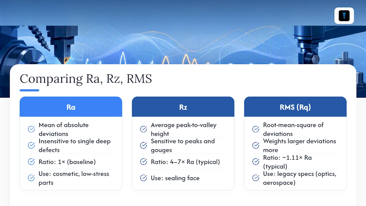
Two other parameters fill that gap. Rz captures the average of the highest peaks and lowest valleys, which makes it far more sensitive to outliers than Ra. RMS (also written Rq) squares each deviation before averaging, which weights larger deviations more heavily than Ra does.
In practice: RMS runs about 1.11 times Ra for most machined surfaces, and Rz tends to fall somewhere between four and seven times Ra, with five times used as a common shop rule of thumb. Neither ratio is fixed. It shifts with the cutting process and the shape of the profile itself.
Use Ra when you need a general smoothness target for a cosmetic or low-stress surface. Reach for Rz when peak-to-valley behavior actually drives function, like a sealing face where one deep gouge defeats the whole gasket. RMS mostly shows up on legacy drawings or specs carried over from older industries like optics and aerospace.
Pro Tip: Misreading Ra for Rz (or vice versa) is one of the most common sources of unnecessary part rejects in incoming inspection. When a print looks unusually tight or loose for the application, double check which parameter is actually called out before you argue with QC.
What Ra Range Can Each Machining Process Achieve?
Every process has a natural surface finish ceiling, and knowing it before you quote a job saves you from promising something your equipment can't deliver without secondary operations.
Ra 1.6 µm (63 µin) is the finish most shops treat as their standard as-machined CNC benchmark, achievable with a well-tuned finish pass on most materials without any secondary process.
The cost jump between bands is where a lot of quotes go sideways. Tightening from Ra 3.2 µm to 1.6 µm on the same machine usually means a slower finish pass and sharper inserts, adding modest cycle time. Push further to Ra 0.8 µm and you're often looking at a 15 to 25 percent cycle time increase just from the finishing pass alone, and below that you're frequently adding a grinding operation entirely. That's a new setup, a new machine, and a new line item on the quote.
A few practical notes worth committing to memory:
- Casting and sandblasting produce textured, functional surfaces, not aesthetic ones. Don't call out a tight Ra on a rough-cast bore that's getting machined anyway.
- EDM finish varies enormously with power settings; a rough burn and a finish burn on the same wire EDM machine can differ by an order of magnitude in Ra.
- Honing and lapping exist specifically to correct geometry and finish together, which is why they cost more per part than a straight grinding pass.
How Is Ra Measured on the Shop Floor?
Two measurement families dominate: contact and non-contact. A stylus profilometer drags a diamond tip across the surface and tracks vertical displacement, remaining the shop-floor workhorse because it's fast, portable, and cheap relative to optical systems. Non-contact methods, including white-light interferometry and confocal microscopy, scan the surface with light instead of a physical tip, which avoids damaging soft or coated surfaces and captures more of the 3D texture, though at higher cost and slower cycle time per part.
Three parameters govern whether a reading is trustworthy: cutoff length (the wavelength filter that separates roughness from waviness), evaluation length (how much surface gets sampled, typically five cutoff lengths), and stylus tip radius (a smaller radius resolves finer detail but wears faster).
| Ra Band (µm) | Typical Cutoff Length | Typical Evaluation Length |
|---|---|---|
| — | 0.25 mm | 1.25 mm |
| 0.1–2.0 | 0.8 mm | 4.0 mm |
| 2.0–10 | 2.5 mm | 12.5 mm |
| Over 10 | 8.0 mm | 40.0 mm |
Get the cutoff wrong and you'll either fold waviness into your roughness reading or filter out real texture, giving you a number that doesn't match the part's actual performance.
- Measure along, not across, the lay direction unless the drawing specifically calls for a cross-lay reading.
- Take multiple readings across the surface rather than trusting a single pass, especially on parts with visible tool marks.
- Recalibrate against a known reference standard on a fixed schedule, not just when a reading looks suspicious.
Pro Tip: If two operators get wildly different Ra readings on the same part, check cutoff length and lay direction first. Those two settings cause more measurement disputes than any actual surface difference.
How Do You Specify Surface Finish on a Drawing?
The surface texture symbol looks simple but every position on it carries meaning, and ASME Y14.36M standardizes exactly what goes where. The Ra value sits above the horizontal bar of the checkmark symbol. The manufacturing process or treatment, when specified, goes on the line below. Sampling length appears to the upper right, and material removal requirements sit to the left of the symbol's long leg.
Lay direction deserves just as much attention as the number itself. A parallel lay symbol (=) means tool marks run parallel to the symbol's edge view; perpendicular (⊥) means marks run across it; circular (C) indicates marks radiating from a center point. On a sealing face or a bearing journal, lay direction can matter as much as the Ra value, because scratches running the wrong direction can create leak paths a smoother-but-misdirected surface wouldn't.
A few callouts you'll see on real prints:
- "Ra 1.6 µm, all over" means every unspecified surface on the part meets that finish, common on general-purpose brackets.
- "Ra 0.4 µm, ⊥ to bore axis" on a hydraulic cylinder bore demands both a tight finish and a specific lay orientation for proper seal contact.
- "Rz 6.3 µm max" on a European print calls out peak-to-valley roughness, not Ra, even though the symbol looks identical to an Ra callout.
Pro Tip: When a print leaves the parameter unspecified, don't assume Ra by default. Check the drawing's governing standard block or call the engineer. Guessing wrong here is how conforming parts get rejected.
How Do You Choose the Right Ra Value for the Application?
Start looser than you think you need, then tighten only where the function demands it. Overspecifying costs money on every single part for the life of the job.
Run through this before you quote or set up:
- Identify the functional surface. Is it sealing, bearing, load-bearing, coated, or purely cosmetic?
- Check the mating surface. A finish only matters relative to what it contacts.
- Determine the real tolerance. Ask whether the function needs Ra 1.6 µm or whether someone just copied a tighter spec from a similar part.
- Estimate feasibility and cost. Match the required Ra against the process ranges chart before committing to a secondary operation.
A few functional benchmarks worth knowing: static o-ring seals often need Ra 0.8 µm or better to seat properly, while a rotating shaft in a plain bearing can often run fine at N6 to N7 (Ra 0.8–1.6 µm). Contact bearing races typically demand grinding to reach Ra 0.2 µm or tighter. Coating adhesion sometimes wants more texture, not less, since some coatings key better to a slightly rougher substrate.
Pro Tip: Run a prototype and measure it before committing shop time to an aggressive finish spec. It's cheaper to find out early that your process won't hold Ra 0.4 µm than after you've cut ten parts.
What Should Your QC Sampling Strategy Look Like?
Surface finish QC fails most often not from bad measurement but from inconsistent sampling. A first article inspection should measure Ra at multiple locations, not just the easiest-to-reach spot, especially on parts with varying wall thickness or tool access.
For running production, batch sampling frequency should scale with process stability. A mature, capable process might get spot-checked every 25 to 50 parts, while a new setup or a tight-tolerance job warrants checking every part until you've established real capability.
Build your checklist around these points:
- Calibrate instruments against traceable reference standards on a documented schedule.
- Clean the surface before measuring; oil film, chips, and coolant residue all skew readings.
- Measure in the correct orientation relative to lay direction every time, not just on the first part.
- Record every reading with part serial number, instrument ID, and calibration date for traceability.
For acceptance, define your tolerance bands upfront: full acceptance, conditional acceptance with rework, and rejection. A part reading Ra 1.7 µm against a 1.6 µm max spec might warrant a documented deviation rather than an automatic scrap, depending on the application.
Pro Tip: Calibrate your profilometer against a NIST-traceable reference standard, not just the manufacturer's included test piece, and log every calibration date so an audit doesn't catch you flat-footed.
What Are the Formulas for Converting Between Ra, Rz, and RMS?
The unit conversion is exact: 1 µm = 39.37007874015748 µin. Converting Ra 0.8 µm gives you roughly 31.5 µin, which shops typically round to 32 µin for callouts.
The parameter conversions are not exact, and treating them as if they were is where mistakes happen:
- RMS ≈ 1.11 × Ra (holds reasonably well across most machined surfaces)
- Rz ≈ 4 to 7 × Ra, with 5× used as a common working approximation
Both ratios shift with process and profile shape, and neither should substitute for measuring the actual parameter the drawing calls out when acceptance is on the line.
Pro Tip: When quoting a supplier or subcontractor, state both the unit and the governing parameter explicitly, like "Ra 0.8 µm (32 µin)." Leaving out the parameter name invites someone to assume Rz and machine to the wrong target.
What Mistakes Trip Up Machinists and Inspectors Most Often?
Four errors account for most Ra-related headaches on the floor:
- Confusing Ra with Rz leads to chasing a finish that's either far tighter or far looser than the print actually requires. Verify the parameter name before adjusting any process.
- Measuring across lay direction instead of along it inflates readings and triggers false rejects. Check the lay symbol before taking a reading.
- Using the wrong cutoff length filters out real texture or lets waviness masquerade as roughness. Match cutoff to the Ra band you expect.
- Treating conversion multipliers as exact causes acceptance disputes when a converted number doesn't match a direct measurement. Measure the specified parameter directly whenever the stakes justify it.
Pro Tip: When a reading surprises you, check these four things before you assume the part is bad.
Which Standards Should You Reference for Surface Finish Specs?
Three standards cover nearly everything you'll need. ISO 21920-1 governs current profile-texture indication and replaces the older ISO 1302 N-grade system, though N-grades still appear on legacy prints. ASME Y14.36M covers drawing symbols, while ASME B46.1 defines the measurement parameters themselves, including Ra.
Pro Tip: Put the governing standard right next to the finish symbol on your own drawings. It removes any ambiguity for a supplier working from an unfamiliar template.
A Shop-Tested Note on Balancing Finish, Cost, and Time
Every shop I've talked to learns the same lesson eventually: specify the loosest Ra that still does the job, then tighten only where a part actually fails without it. Moving a bore from Ra 1.6 µm to 0.8 µm sounds like a small change on paper. In practice it often means adding a grinding operation you didn't budget for. Measure early, on a real prototype, before that surprise shows up on a production run.
How Availzye Machinist Pro Takes the Guesswork Out of Finish Callouts
Cross-referencing an Ra chart against process capability every time a quote comes in gets old fast, especially when you're juggling five jobs and a print that mixes Ra and Rz callouts. The Surface Finish Calculator inside Availzye Machinist Pro converts between µm, µin, Ra, and Rz instantly, and flags which processes can realistically hit the target you're quoting.

That matters most when you're pricing a job under deadline pressure. Instead of eyeballing a conversion chart or arguing with a supplier over whether 32 µin means Ra or Rz, you get a consistent answer every time, which cuts down on the back-and-forth that turns into QC disputes later. Pair it with the Cost Estimator to see how tightening a finish spec actually affects your cycle time before you commit to a price, and the G-code Generator to keep your finishing passes consistent across parts and operators.
The Surface Finish Calculator comes with every subscription tier, starting at $9.99 a month for individual machinists, with a 7-day free trial if you want to run it against your next quote before committing. Try the Surface Finish Calculator and see how it handles your next mixed Ra/Rz print.