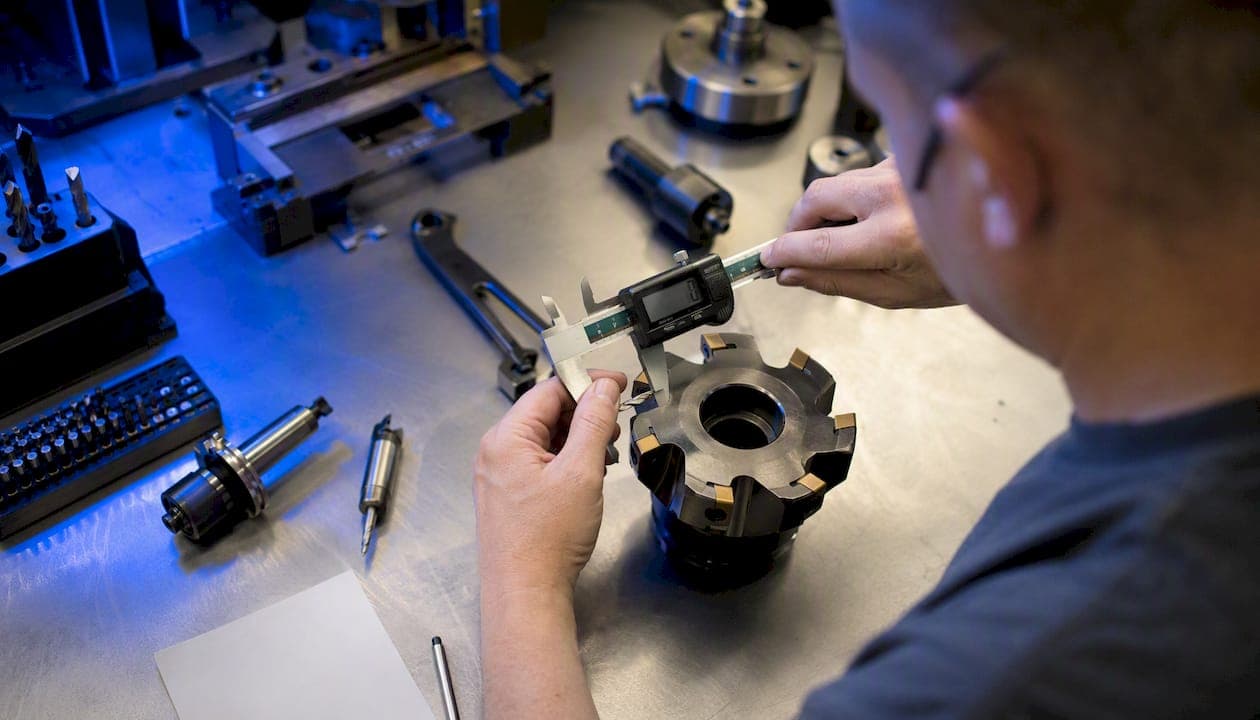
Chip load (measured in inches per tooth, or IPT) tells you exactly how thick a slice each cutting edge takes per revolution. The core milling formula is:
IPT = Feed Rate (IPM) ÷ (RPM × Number of Flutes)
Reverse it to get your programmed feed rate: IPM = RPM × IPT × Number of Flutes
To convert surface footage to spindle speed: RPM = (SFM × 3.82) ÷ Cutter Diameter
Quick example from Harvey Tool's cutting tool reference: 6,000 RPM × 0.004 IPT × 3 flutes = 72 IPM. These are arithmetic results only. Before running the program, verify that your machine, toolholder, and workholding can handle the resulting forces and feed rates.
- Core formula: IPT = IPM ÷ (RPM × Z)
- Reverse formula: IPM = IPT × RPM × Z
- RPM from SFM: RPM = (SFM × 3.82) ÷ D
Key Takeaways
Chip load calculation is the starting point for every feeds and speeds decision, and the IPT formula, thinning correction, and manufacturer data together determine whether your parameters hold up in production.
| Point | Details |
|---|---|
| Core IPT formula | IPT = IPM ÷ (RPM × flutes); reverse to get feed: IPM = IPT × RPM × flutes. |
| Chip thinning correction | When Ae < D/2, programmed feed must increase; use f_z = target IPT ÷ √(1 − (1 − 2·Ae/D)²). |
| Manufacturer data first | Generic tables are for learning; toolmaker charts are the authoritative source for production sign-off. |
| Small cutters need caution | Start at the low end of the diameter band and increase in 10% steps to avoid breakage. |
| Availzyemachinistpro | Integrates forward/reverse chip-load calculators, chip-thinning correction, and tool database in one platform. |
Table of Contents
- What is chip load and why does it matter?
- Core formulas for milling, drilling, turning, and SFM conversion
- How does a chip-load calculator work?
- When does radial chip thinning apply, and how do you fix it?
- Starting chip-load ranges by material and cutter diameter
- Worked arithmetic examples: milling, drilling, and turning
- Common mistakes, signs of wrong chip load, and quick fixes
- How to verify calculated chip load on the machine
- The arithmetic is necessary but not sufficient
- Availzyemachinistpro puts chip-load tools where you actually need them
- Sources
What is chip load and why does it matter?
Chip load is the thickness of material removed by one cutting edge in a single revolution, expressed in IPT for milling and drilling, or inches per revolution (IPR) for turning. Get it right and tools last longer, surfaces come out cleaner, and heat stays in the chip where it belongs. Get it wrong in either direction and you pay for it fast.
Too low a chip load and the edge rubs instead of cuts. Friction builds, heat transfers into the tool, and you get built-up edge (BUE) on the flute face. In wood, the symptom is burning and glazing. In aluminum, it shows up as welded material on the flute. Too high a chip load and cutting forces spike, the edge chips or fractures, and surface finish degrades. Both failure modes shorten tool life, but rubbing is the more common mistake because machinists instinctively slow the feed when something sounds wrong.
According to ToolGrit's chip load machining guide, chip load strongly affects tool life, finish, cutting forces, and heat generation, but it must always be evaluated alongside machine and setup factors. The formula gives you a number; the shop gives you the reality check.
Variables that always travel with chip load decisions:
- Machine rigidity and spindle power
- Toolholder type and runout (collet vs. shrink fit vs. set-screw)
- Workholding stiffness
- Coolant type and delivery pressure
- Chip evacuation (especially in deep pockets or holes)
- Toolmaker's published starting data for that specific cutter
Pro Tip: When chip load is too low, increase feed rate rather than dropping RPM. Maintaining surface footage (SFM) protects tool life; cutting RPM to fix a rubbing problem usually makes it worse.
Core formulas for milling, drilling, turning, and SFM conversion
Every chip load calculation chains through the same four relationships. Keep units consistent throughout — mixing inches-per-minute with millimeters-per-minute is the most common arithmetic error in the shop.
Milling
- IPT = IPM ÷ (RPM × Z)
- IPM = IPT × RPM × Z
- Z = number of flutes
Drilling
Drills are typically specified in feed per revolution (IPR), not per flute. To find the per-flute equivalent: IPT = IPR ÷ number of flutes. A standard 2-flute jobber drill running at 0.006 IPR is cutting 0.003 IPT per edge. Note that drill geometry, point style, and hole depth all affect what feed actually works — the per-flute number is a starting reference, not a guarantee.
Turning
Single-point turning uses feed per revolution directly as the chip thickness input. Nose radius and finish requirements change the usable feed ceiling, but the chip-load concept is the same: material removed per edge per revolution.
SFM to RPM conversion (imperial)
RPM = (SFM × 3.82) ÷ Diameter (inches)
Example: a 1/2" end mill targeting 800 SFM in aluminum → RPM = (800 × 3.82) ÷ 0.5 = 6,112 RPM
For metric, the equivalent is: RPM = (SMM × 318.3) ÷ Diameter (mm), where SMM is surface meters per minute. The MachiningDoctor chip load calculator walks through this chained workflow — SFM to RPM, then RPM to feed rate — as a structured sequence that reduces transcription errors.
As CNCCookbook's chip load calculator explains, IPT is conceptually independent of RPM and flute count. The toolmaker specifies IPT based on the cutter geometry and material. What changes with flute count is the programmed feed rate (IPM), not the per-tooth target.
How does a chip-load calculator work?
A well-built calculator runs in two directions. Understanding which mode you need before you open one saves time.
Forward mode takes a known feed rate and spindle speed and calculates the chip load you are currently cutting. Use this to audit an existing program or a CAM-generated toolpath.
Reverse mode takes a target IPT and computes the feed rate you need to program. This is the setup mode — you start from the manufacturer's recommended chip load and work forward to a table feed.
Required inputs for a complete calculation:
- Cutter diameter
- Number of flutes
- Spindle speed (RPM) or desired SFM (calculator converts it)
- Feed rate (for forward mode) or target IPT (for reverse mode)
- Axial depth of cut (DOC)
- Radial engagement or stepover (WOC)
- Tool type (end mill, drill, face mill, etc.)
Beyond the basic IPT result, a solid calculator also outputs effective chip thickness after thinning correction, adjusted feed rate when thinning compensation is applied, and material removal rate (MRR) in cubic inches per minute. The ToolGrit chip load calculator flags results against recommended ranges with green/yellow/red indicators — useful for a quick sanity check, though a green flag does not replace machine capability verification or a first-piece test.
CAM software often includes chip-load fields, but those fields rarely apply thinning correction automatically unless you enable it. Running a standalone calculator alongside your CAM output catches the discrepancy before the program runs.
When does radial chip thinning apply, and how do you fix it?
Radial chip thinning is the geometry problem that bites machinists running adaptive, trochoidal, or any shallow-stepover toolpath. When your radial engagement (Ae) drops below half the cutter diameter (D/2), the chip never reaches its full programmed thickness. The cutter arcs through the material at a shallower angle, and the actual chip is thinner than the IPT you programmed.
The correction formula, per Pi Fabricators' chip load calculator documentation:
h_ex = f_z × √(1 − (1 − 2·Ae/D)²)
Where h_ex is the effective chip thickness and f_z is the programmed chip load. To maintain your target chip thickness, you invert this to find the required programmed feed:
f_z (required) = h_ex (target) ÷ √(1 − (1 − 2·Ae/D)²)
Worked example: 1/2" cutter, Ae = 0.050" (10% of diameter), target chip load = 0.004 IPT.
- 2·Ae/D = 2 × 0.050 / 0.5 = 0.20
- √(1 − (1 − 0.20)²) = √(1 − 0.64) = √0.36 = 0.60
- Required programmed f_z = 0.004 ÷ 0.60 = 0.0067 IPT
You need to program 0.0067 IPT to actually cut 0.004 IPT at that stepover. At very narrow engagements, this multiplier can exceed 2×, which pushes programmed feeds into ranges where deflection and torque limits become the real constraint.
Pro Tip: Most CAM packages have a chip-thinning compensation toggle. Turn it on for adaptive toolpaths. But verify the output against the chip thinning formula manually at least once per new material or cutter combination — CAM defaults are not always conservative.
Starting chip-load ranges by material and cutter diameter
Manufacturer tables are the authoritative source. The ranges below are representative starting points for carbide tooling; always verify with the toolmaker's catalog before production sign-off.
For 6061-T6 specifically, Harvey Tool's reference data shows 0.003–0.006 IPT for 1/4" carbide cutters and 0.005–0.012 IPT for 1" cutters. Those ranges assume sharp carbide, good workholding, and proper chip evacuation.
A few rules that hold across materials:
- Flute count changes feed rate, not IPT. A 2-flute and a 4-flute end mill in the same material at the same RPM target the same IPT, but the 4-flute runs twice the table feed. For aluminum, 2–3 flutes are preferred because the wider gullets evacuate chips before they re-cut and weld.
- Small cutters are fragile. A 1/8" end mill has almost no stiffness margin. Start at the low end of the range and work up in 10% increments. Harvey Tool's guidance is explicit: small-diameter cutters are prone to breakage if overloaded, and diameter-specific limits from the toolmaker are non-negotiable.
- Coatings shift the ceiling. TiAlN and AlTiN coatings allow higher SFM in steel and titanium, which indirectly permits higher chip loads before heat becomes the limiting factor. Uncoated carbide in stainless needs more conservative starts.
For aluminum temper selection and its effect on machinability, the T6 vs T6511 aluminum guide covers how the two tempers differ in cutting behavior — relevant when you are dialing in starting ranges for a new material cert.
Worked arithmetic examples: milling, drilling, and turning
Milling example
Inputs: 1/2" 3-flute carbide end mill, 6061-T6 aluminum, target SFM = 800, target IPT = 0.005

Step 1 — RPM: (800 × 3.82) ÷ 0.5 = 6,112 RPM
Step 2 — Feed rate: 6,112 × 0.005 × 3 = 91.7 IPM
Result: Program 6,100 RPM and 91 IPM. At full-width slotting, no thinning correction needed. At 20% stepover (0.100"), apply the correction from the previous section.
Drilling example
Inputs: 1/2" 2-flute HSS jobber drill, 1018 mild steel, manufacturer IPR = 0.006

Step 1 — Per-flute chip load: 0.006 ÷ 2 = 0.003 IPT
Step 2 — RPM from SFM: target SFM = 80 → (80 × 3.82) ÷ 0.5 = 611 RPM
Step 3 — Feed rate: 0.006 IPR × 611 = 3.7 IPM
Deep holes (beyond 3× diameter) typically require peck cycles and reduced feed. Drill geometry, coolant delivery, and hole depth all affect what actually works, so treat this as a starting point and consult the drill maker's data for production.
Turning example
Inputs: 2" diameter 1018 bar, carbide insert, target SFM = 350, feed = 0.008 IPR
RPM: (350 × 3.82) ÷ 2.0 = 669 RPM
Feed rate: 0.008 IPR × 669 = 5.4 IPM
Nose radius limits the maximum feed for finish passes. A 0.031" nose radius typically caps finish feed around 0.004–0.006 IPR to hit Ra targets below 63 µin. The chip-load arithmetic stays the same; the finish constraint is a separate ceiling.
The feeds and speeds shop guide covers how to chain these calculations into cycle-time estimates and CAM settings.
Common mistakes, signs of wrong chip load, and quick fixes
Diagnosing a chip-load problem at the machine is faster when you know what each failure mode looks like.
Signs of chip load too low:
- Burning or discoloration on the workpiece or tool
- Glazed or work-hardened surface (especially in stainless and titanium)
- Built-up edge on the flute face
- Excessive heat with little material removal
Signs of chip load too high:
- Chipped or fractured cutting edges
- Broken tool, especially on small-diameter cutters
- Rough, torn surface finish
- Chatter or vibration at the spindle
Quick corrective actions:
- Too low: increase feed rate first; check that SFM is within the toolmaker's range
- Too high: reduce feed in 10–15% steps; check radial and axial depth of cut; inspect runout
- Chatter: reduce DOC or WOC before touching feed; check workholding and holder type
- BUE in aluminum: verify coolant flow and chip evacuation; consider a coated cutter or higher SFM
- Broken small-diameter tool: start at the low end of the manufacturer's range; check runout with a test indicator
One change at a time. Changing feed, DOC, and coolant simultaneously makes it impossible to know what fixed the problem. Verify spindle torque and axis feed limits before pushing feed rates above the machine's rated capacity.
How to verify calculated chip load on the machine
Arithmetic gets you to the starting line. The first-piece test is what confirms the calculation works on your specific machine, with your specific setup.
- Set up and indicate. Indicate the workpiece, check runout on the toolholder (target under 0.0005" TIR for most end mills), and confirm coolant is flowing.
- Dry run at feed hold. Run the program with the spindle off to verify toolpath clearances and rapid moves.
- First pass at 50% feed override. Run the first cutting pass at half the programmed feed. Listen for chatter, watch chip color and size.
- Inspect tool and part. Check the cutting edge under magnification if available. Measure the part dimension. Look at surface finish.
- Step up in 10% increments. Increase feed override toward 100% while monitoring sound, finish, and chip formation.
- Log the result. Record the final working parameters before moving to production.
Suggested logging columns: Tool ID, Diameter, Flutes, Material, RPM, IPT, IPM, DOC, WOC, Coolant Type, Notes. This log becomes your shop's institutional memory for repeat jobs.
Disclaimer: chip load calculations are arithmetic only. Always verify that your machine, toolholder, and workholding can handle the resulting forces before production. Consult the toolmaker's data for final parameter sign-off.
The arithmetic is necessary but not sufficient
Chip load calculation is the foundation, not the finish line. The formula gives you a defensible starting point, but the machine doesn't care about your spreadsheet. Rigidity, runout, coolant pressure, and chip evacuation all shift the effective result away from the theoretical number, sometimes by more than you'd expect.
The machinists who get the most out of chip-load arithmetic are the ones who treat it as a hypothesis to test, not a setting to trust. Run the calculation, apply conservative starting parameters, and let the first-piece test tell you where the real ceiling is. Calculators reduce the number of test iterations you need, but they do not eliminate them.
One thing that genuinely helps is keeping the calculation, the tool data, and the test log in the same place. When those three live in separate spreadsheets and sticky notes, institutional knowledge walks out the door with the operator who set the job up. Availzyemachinistpro's integrated calculators and tool database are built specifically to close that gap.
Availzyemachinistpro puts chip-load tools where you actually need them
Every chip-load workflow covered here, from the forward/reverse IPT calculation to chip-thinning correction and first-piece logging, is built into Availzyemachinistpro as a connected set of tools rather than isolated calculators.

The Feeds & Speeds calculator handles SFM-to-RPM conversion, forward and reverse chip-load modes, and MRR output in one screen. The chip-thinning module applies the geometric correction automatically for adaptive toolpaths. The Tool Database stores manufacturer-specified IPT ranges by diameter so you are always starting from toolmaker data, not a generic table. First-piece test logs attach directly to the job record, so the parameters that worked on the last run are one click away on the next.
Three subscription tiers start at $9.99/month, with a 7-day free trial. If you are ready to replace the scattered spreadsheets with a shop-ready platform, the G-Code Generator and full calculator suite are waiting. Start your free trial at Availzye-machinist-pro.
Sources
- Harvey Tool — cutting tool reference
- ToolGrit — Chip load machining guide
- MachiningDoctor — Chip Load Calculator
- CNCCookbook — CNC chip-load calculator