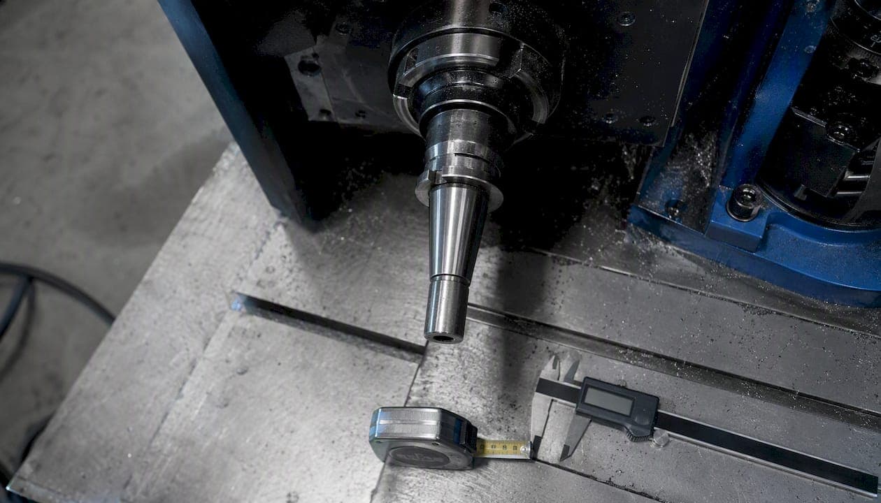
Morse tapers MT0 through MT7, plus the rare MT4.5, are the standard sizes you'll encounter in drill presses, lathes, and milling machine spindles. The chart in the next section lists typical large diameter, small diameter, and usable length ranges for each size, measured in both inches and millimeters. The standard taper rate is approximately 5/8" per foot across the family, and that shallow angle is precisely what makes these tapers self-holding without a drawbar. Before you pull measurements from the chart, note one critical caution: female spindle bores often measure slightly undersize compared to the nominal shank dimensions, so always verify with a known arbor or a taper calculator like the one in Availzyemachinistpro before ordering tooling.
- MT0–MT7 cover the full range from instrument-scale tooling to heavy industrial machines
- MT4.5 exists but is rare, found mainly in legacy equipment
- Female cavities can run undersize; measure the bore, not just the shank
- The Engineers Edge dimension table and the Zoro/AIMS references are the most complete publicly available charts
Key Takeaways
Morse taper identification starts with measuring the large-end diameter at the socket face and comparing it to the MT0–MT7 chart; every other step follows from that single measurement.
| Point | Details |
|---|---|
| MT0–MT7 plus MT4.5 | The full standard family; MT4.5 is rare and found mainly in legacy machines. |
| Measure first, assume nothing | Large-end diameter at the socket face is the primary identification point; machine model is not reliable. |
| Female bores run undersize | Spindle cavities often measure slightly smaller than nominal shank values; this is normal and expected. |
| No lubricant on mating surfaces | Oil or grease on a self-holding taper reduces friction and causes spinning and galling. |
| Availzyemachinistpro Taper Calculator | Enter two measured diameters to compute taper ratio and included angle, then save the result to your shop records. |
Table of Contents
- Morse taper dimensions: the complete MT0–MT7 reference chart
- How do you identify and measure a Morse taper?
- Why are Morse tapers self-holding, and what does the angle mean?
- Tolerances, fit variations, and common fitment problems
- Which MT sizes are common in typical shop equipment?
- Using a taper calculator to verify measurements and save shop records
- How material and surface finish affect taper fit and performance
- ANSI, ISO, and DIN standards that govern Morse taper manufacturing
- A shop perspective on what actually goes wrong with Morse tapers
- Availzyemachinistpro's taper calculator: verify measurements and store results
- Sources
Morse taper dimensions: the complete MT0–MT7 reference chart
The table below is your shop-ready reference. Large diameter is measured at the large end (socket face or shank shoulder), small diameter at the plug depth, and usable length is the full seating depth of the taper shank. Values follow published Morse taper shank standards and are consistent with the Zoro dimensional reference.
Reading the columns:
- Large diameter: measured at the large-end face of the shank or at the socket opening, away from any burrs or chamfer
- Small diameter: measured at the plug depth (the full seated length), not at the tip of the shank
- Usable length: the full seating depth; short-stub shanks will have a shorter effective plug depth
- Taper/foot: varies slightly by size but stays close to 5/8" across the family
MT4.5 is a rare size found in some older medium lathes and legacy equipment. If the large-end diameter measures around the typical value for MT4.5, physically confirm the size before ordering because holders for MT4 or MT5 may not fit correctly.
Pro Tip: Print this table and laminate it for the tool crib. A PDF saved to your shop's reference docs folder means anyone on the floor can verify a taper in under a minute without hunting for the manual.
How do you identify and measure a Morse taper?
Measuring a taper correctly takes about three minutes with a good set of calipers. The most common mistake is measuring at the wrong point, which produces a diameter that matches no size in the chart.
-
Clean the taper surfaces. Wipe both the shank and the socket with a clean rag. Any chip or burr on the large-end face will throw your reading off by several thousandths.
-
Measure the large diameter. Place your calipers at the large-end face of the shank (or at the socket opening for a female bore). This is the number you compare first against the chart above.
-
Measure the small diameter. Measure at the plug depth, not at the very tip. On a shank, that means measuring at the point corresponding to the full seated length.
-
Measure the usable length. This is the distance from the large-end face to the small-end measurement point.
-
Calculate taper per inch. Use this formula:
Taper per inch = (Large diameter − Small diameter) ÷ Usable length
Example for MT2: (0.700 − 0.572) ÷ 2.500 = 0.0512 in/in, which equals 0.614 in/ft. That's consistent with the ~5/8" per foot family value.
-
Compare to the chart. Match your large diameter and computed taper rate to the MT0–MT7 table. If you're between two sizes, you likely have MT4.5 or a worn/non-standard taper.
-
Verify with a known arbor. A CGTK shop reference notes that measuring the large-end diameter at the socket face is more reliable than trusting machine model assumptions. If a known MT2 arbor seats cleanly with no wobble, you have MT2.
-
Check the machine data plate. Many machines stamp the spindle taper on the nameplate or in the headstock casting. Use it as a cross-check, not as a substitute for measurement.
Pro Tip: Never measure on a chamfered edge or near a tang slot. Set your calipers on the clean cylindrical land of the major diameter, and take three readings at different rotational positions to catch any out-of-round condition.
Why are Morse tapers self-holding, and what does the angle mean?
The geometry here is simple but worth understanding, because it directly affects how you install, remove, and troubleshoot tooling.
The Morse taper family uses a taper rate of roughly 5/8" per foot, which translates to a half-angle of approximately 1.49°. The full included angle across the family runs from about 2.86° (MT1) to 3.00° (MT5), varying slightly by size. That shallow angle keeps the friction angle between mating surfaces greater than the taper angle itself, which is the mechanical condition that produces self-holding behavior. In plain terms: the taper wedges itself in place under axial load, and friction prevents it from backing out.

Contrast that with steeper tapers like the 7:24 (CAT/BT) or HSK systems used in CNC machining centers. Those run at a much steeper included angle, which is why they require a drawbar or retention knob to stay seated. They release quickly and cleanly, which suits high-speed tool changes, but they offer no self-holding friction at all.
Key angle and ratio figures by size:
- MT0: taper per foot 0.6246", included angle ~2.98°
- MT2: taper per foot 0.5994", included angle ~2.86°
- MT3: taper per foot 0.6023", included angle ~2.87°
- MT5: taper per foot 0.6315", included angle ~3.00°
The slight variation in taper rate across sizes is intentional. Each size was designed to maintain the self-holding property under the loads typical for tooling of that diameter.
Tolerances, fit variations, and common fitment problems
Real-world spindle bores and shanks don't always match the nominal chart values exactly. Manufacturing tolerances on taper shanks and sockets are typically specified as ±0.002" per foot on the taper rate, and plug depth tolerances also vary between short-stub and full-length shanks.
Common fit issues and how to handle them:
- Spindle bore undersize: Female cavities often measure slightly smaller than the nominal shank diameter. This is normal and intentional; the taper seating geometry compensates. Don't try to lap or enlarge the bore unless you have a precision taper reamer and know the exact target diameter.
- Shank won't seat fully: Usually caused by a chip, burr, or raised metal near the socket opening. Clean both surfaces and inspect under good light before forcing anything.
- Tool spins in the socket: The classic symptom of a lubricated or contaminated taper. Clean both surfaces with acetone or a clean solvent rag, dry completely, and reseat. Never apply cutting oil, grease, or anti-seize to a self-holding taper during normal use.
- Stuck taper removal: Use a drift (a flat steel bar or the machine's dedicated drift key) inserted through the drift slot in the spindle. A sharp tap with a mallet is usually enough. Never use a screwdriver or pry bar against the shank, and never hammer directly on the tool.
- Galling or surface damage: If the taper surfaces show scoring or galling, the spindle or shank needs professional inspection. A damaged taper bore is a machine repair job, not a shop-floor fix.
Pro Tip: Before seating any taper shank, run your fingernail lightly across both mating surfaces. You should feel nothing. Any raised edge, even a small one, will prevent full seating and cause runout.
If the spindle bore shows visible damage or the taper no longer holds tooling securely after cleaning, consult the machine manufacturer's service documentation or a qualified machine tool repair shop before continuing to use the spindle. For better upkeep and scheduling repairs, consider using specialized Mining Equipment Maintenance Software to maintain detailed service records and ensure optimal machine performance.
Which MT sizes are common in typical shop equipment?
Knowing where each size shows up saves time when you're sourcing tooling or troubleshooting a fit. MT2 and MT3 dominate general workshop equipment, covering the vast majority of drill presses, lathes, and milling attachments found in job shops and tool rooms.
- MT0: Small instrument lathes, watchmaker's equipment, and some precision grinding spindles. Rarely seen in general metalworking shops.
- MT1: Small bench lathes, sensitive drill presses, and some precision toolholders. Uncommon in production environments.
- MT2: The most common size in benchtop drill presses and small-to-medium lathes. Most drill chuck arbors for bench machines are MT2. If you're buying tooling for a benchtop machine and don't know the taper, MT2 is the most likely answer, but measure first.
- MT3: Standard on floor-standing drill presses and medium-capacity lathes. Many tailstock quills on 12"–16" swing lathes are MT3. Also common in milling machine spindles on knee mills.
- MT4: Larger floor-standing drill presses, heavy-duty lathes, and some horizontal milling machines. Less common than MT3 but widely stocked by tooling suppliers.
- MT4.5: Legacy size found in some older medium lathes, particularly certain European and American machines from the mid-20th century. Tooling is harder to source; always measure the large diameter (approximately 1.500") before ordering.
- MT5: Large industrial lathes, heavy drill presses, and some boring machines. The spindle on a large engine lathe headstock is often MT5.
- MT6 and MT7: Heavy industrial and mining equipment, large boring mills, and specialized machinery. Rarely encountered in a typical job shop.
The AIMS Industrial guide notes that tooling compliant with DIN 228 / ISO 296 is interoperable across manufacturers for the same MT designation, which matters when sourcing replacement tooling internationally.
Using a taper calculator to verify measurements and save shop records
A chart gives you the reference values. A taper calculator closes the loop by letting you enter your actual measured numbers and confirming whether they match a known MT size.
- Measure large and small diameters at the correct points (large-end face and plug depth).
- Enter both values plus the usable length into the Availzyemachinistpro Taper Calculator.
- Read the computed taper per inch and included angle. The calculator outputs both, so you can compare directly against the MT0–MT7 table.
- Match to the chart. If the computed taper rate falls within the expected range for a given MT size and the large diameter matches, you have a positive identification.
- Save the result. Export or record the calculation with the machine serial number, spindle location, and date. That record becomes part of your maintenance history and saves time the next time someone needs to order a replacement arbor.
As Xometry's taper reference explains, computing taper ratio from two measured diameters is the most reliable identification method when you don't have the original machine documentation.
Pro Tip: Save a PDF of the taper calculation alongside the machine's maintenance log. When you're sourcing a replacement arbor six months later, having the exact measured values on file is faster and more reliable than re-measuring a worn spindle.
The Tool Database in Availzyemachinistpro lets you log each tool's taper size, condition, and machine assignment, so your whole shop's spindle inventory stays current without a separate spreadsheet.
How material and surface finish affect taper fit and performance
The self-holding property of a Morse taper depends on the coefficient of friction between mating surfaces, and that friction is directly tied to material and finish quality.
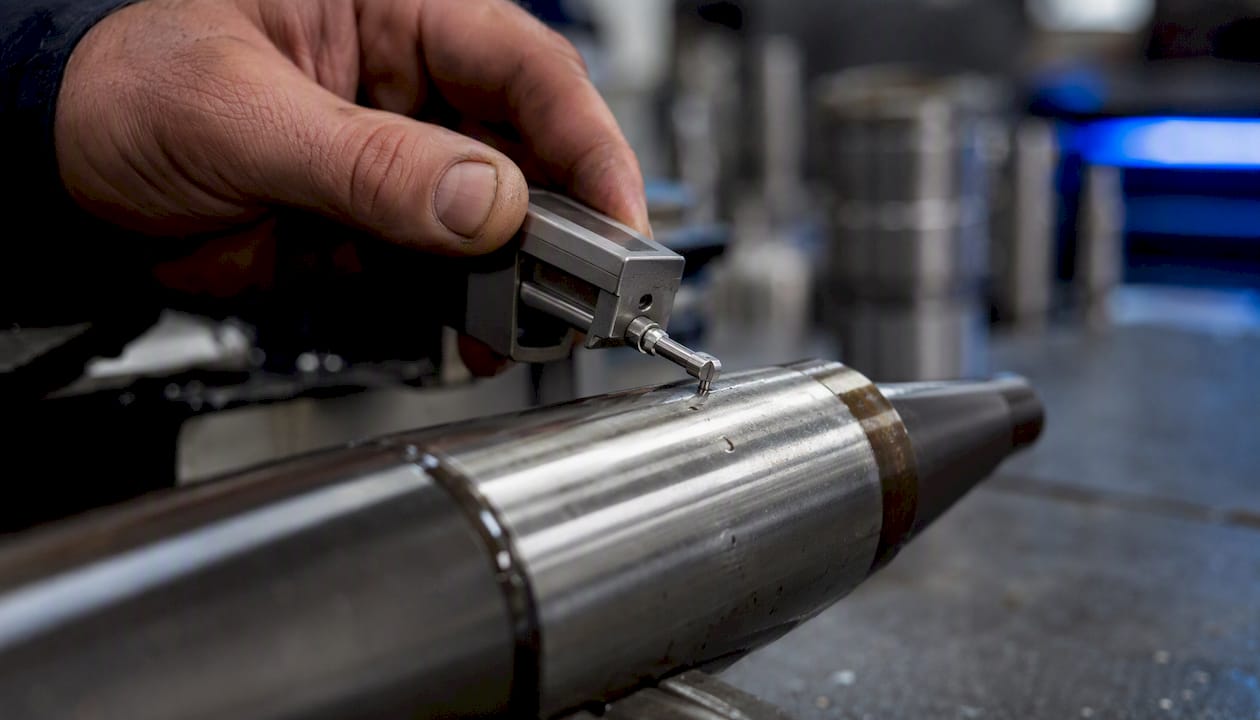
Most Morse taper shanks are made from medium-carbon or alloy steel, hardened and ground to a surface finish in the range of 16–32 Ra microinches (0.4–0.8 Ra micrometers). The spindle bore is typically ground to a similar or slightly finer finish. That combination produces consistent, predictable friction across the taper contact area.
A finish that's too rough increases the risk of galling on first seating, particularly with hardened shanks in softer spindle materials. A finish that's too smooth (below about 8 Ra microinches) can actually reduce the friction coefficient enough to compromise self-holding, especially under vibration. This is why lapping a taper bore with fine abrasive to "improve fit" is usually counterproductive unless you're correcting a specific geometric error under controlled conditions.
Corrosion is the other surface finish concern. Even light rust on a taper shank raises the effective surface roughness and can cause the shank to seize in the bore. Store taper tooling with a light coat of rust-preventive oil on the shank, but wipe it completely dry before seating. The oil is for storage, not for installation.
ANSI, ISO, and DIN standards that govern Morse taper manufacturing
Morse tapers are covered by several overlapping standards, and knowing which one applies to your tooling matters when you're specifying replacements or checking compliance.
ANSI/ASME B5.10 is the primary American standard for machine tapers, including the Morse series. It defines the nominal dimensions, tolerances, and surface finish requirements for both shanks and sockets. Most American-made tooling and machine spindles reference this standard.
ISO 296 covers the same Morse taper geometry for metric-dimensioned tooling and is the reference used by European and Asian manufacturers. Tooling compliant with ISO 296 is dimensionally interoperable with ANSI/ASME B5.10 tooling for the same MT designation, provided both parts are within tolerance.
DIN 228 is the German standard that predates ISO 296 and remains widely referenced for older European machinery. The dimensional values align closely with ISO 296, and DIN 228-compliant tooling generally seats correctly in ANSI-spec spindles of the same MT size.
Tolerance classes matter in practice. ANSI/ASME B5.10 defines tolerance grades for both the shank (plug) and the socket (ring), with tighter grades used for precision spindle applications. A standard-grade shank in a precision-grade socket will seat and hold correctly; a worn or out-of-tolerance shank in any socket will not, regardless of which standard it was originally made to.
When sourcing replacement tooling, specify the MT number and the applicable standard (ANSI/ASME B5.10 or ISO 296) to avoid receiving tooling that's nominally the right size but outside the tolerance band for your spindle.
A shop perspective on what actually goes wrong with Morse tapers
The most expensive Morse taper mistake isn't ordering the wrong size. It's forcing a tool that doesn't seat cleanly and walking away without checking runout.
A shank that's 0.003" undersize on the large diameter will appear to seat. It will feel snug. It will hold for the first few cuts. Then it will spin, gall the bore, and turn a $40 arbor problem into a $400 spindle repair. The tell is always the same: a slight wobble at the tool tip that wasn't there yesterday, or a faint squeaking sound during light cuts.
Quick checks before every taper installation:
- Clean both surfaces. No exceptions, even for a tool you just used an hour ago.
- Measure the large diameter if there's any doubt about the size. Don't assume.
- Test-fit with a known good arbor before seating the actual tool if the spindle has been idle or recently serviced.
- Inspect for burrs at the socket opening and near the drift slot.
- Check runout with a test indicator after seating. More than 0.001" TIR on a freshly seated MT2 arbor is worth investigating before cutting.
Keep a written record when a spindle bore measures outside the nominal range. That note, attached to the machine's maintenance log, tells the next machinist exactly what to expect and prevents the same diagnostic cycle from repeating.
Availzyemachinistpro's taper calculator: verify measurements and store results

Availzyemachinistpro's Taper Calculator takes your two measured diameters and usable length, computes the taper per inch and included angle, and displays the result alongside the MT reference values for direct comparison. No manual math, no transcription errors. The platform also includes a Tool Crib for logging each tool's taper size, condition notes, and machine assignment, so your spindle inventory stays current across the whole shop.
Availzyemachinistpro is a subscription SaaS platform at $9.99/month for individual machinists, with a 7-day free trial. Start the trial at Availzye-machinist-pro and run your first taper verification today.
Sources
The sources below are the most authoritative publicly available references for Morse taper dimensions and standards.
- Machine taper
- What are the Dimensions and Angles of Morse Tapers and Jacobs Tapers?
- Morse Taper Shanks Dimensions Table
- Morse Taper Guide: Sizes, Dimensions & MT0-MT7 | AIMS Industrial
- Taper: Definition, Purpose, Types, and Methods | Xometry
For standards documents, ANSI/ASME B5.10 and ISO 296 are the primary references. Both are available through ASME and ISO directly; your machine tool manufacturer's documentation will specify which tolerance grade applies to your spindle.