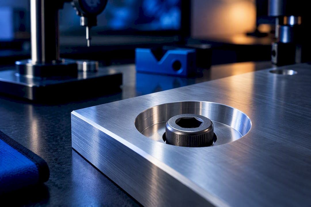
Counterbore diameters and depths follow published standards, not shop guesswork. ASME B18.3 governs imperial socket head cap screw sizes, while ISO 4207 covers metric tooling and pilot geometry. This guide gives you both imperial and metric charts, showing counterbore diameter (X) and depth (H) for common fastener sizes, plus the shop steps to cut and verify them correctly. If you want the numbers converted straight into CNC setup parameters, Availzye Machinist Pro's counterbore calculator does that lookup for you.
TL;DR:
- Counterbore diameters for common fasteners range from 7/16 inch for 1/4-20 screws to 13/16 inch for 1/2-13 screws, with depths typically between 0.259 and 0.529 inches.
- Using the correct clearance drill size is essential: 17/64 inch for 1/4-20 close fit, 13/32 inch for normal fit, and matching metric sizes for metric fasteners to avoid errors.
- Set your CNC or drill to the specified depth (H) using a depth stop and verify fit with actual fasteners before production to prevent incorrect seating or damage.
- Standard dimensions follow ASME B18.3 for imperial sizes and ISO 4207 for metric sizes, with deviations only for specialized fasteners or tight assemblies.
- The Availzye Machinist Pro counterbore calculator simplifies lookup, conversions, and setup parameter export, reducing setup time and errors.
Table of Contents
- Imperial Counterbore Dimensions Chart (Inch Sizes)
- Metric Counterbore Dimensions Chart (mm)
- How to Set Counterbore Depth and Verify the Fit
- Standards, Drawing Callouts, and Fit Rationale
- Machining Considerations: Materials, Tooling, and Inspection
- Availzye Machinist Pro's Counterbore Calculator
- Specialty and Less Common Fastener Counterbore Tables
- Tolerances and Allowances You Should Expect on Counterbore Dimensions
- Counterbore vs. Countersink: Which One Do You Need?
- How Counterbore Dimensions Affect Joint Strength
- How to Measure an Existing Counterbore Accurately
- When to Deviate From Standard Counterbore Charts
- Try the Counterbore Calculator Before Your Next Setup
- Sources
- FAQ
Imperial Counterbore Dimensions Chart (Inch Sizes)
Every imperial counterbore job starts with the same three numbers: the clearance drill size, the counterbore diameter (X), and the counterbore depth (H, sometimes labeled as the max head height clearance). ASME B18.3 sets these values for socket head cap screws, and Engineers Edge publishes the full tabulated version most shops reference daily.
| Screw Size | Clearance Drill (Close) | Clearance Drill (Normal) | Counterbore Diameter (X) | Counterbore Depth (H) |
|---|---|---|---|---|
| #4-40 | #31 | #29 | 0.219 | 0.152 |
| #10 | #21 | #9 | approximately 0.375" | 0.225 |
| 1/4-20 | 17/64 | 9/32 | 7/16 | approximately 0.259" |
| 3/8-16 | 25/64 | 13/32 | 5/8 | approximately 0.394" |
| 1/2-13 | 33/64 | 17/32 | 13/16 | 0.529 |
Each column does a specific job on the print or in your CAM setup. The clearance drill sizes the through hole for the screw shank, not the head. Counterbore diameter (X) is the recess your cutter opens up to seat the screw head flush or below the surface. Counterbore depth (H) is the axial depth of that recess, sized so the head sits flush or slightly recessed once the fastener is torqued down.
Take the 1/4-20 row as an example. Cross-referenced values from Advanced Integrated Technologies confirm the same 7/16-inch counterbore diameter, which is the number machinists quote most often on shop floor. For a #10 screw, the 0.375-inch counterbore diameter leaves enough wall thickness around a #21 drilled hole without weakening thin sections. For 3/8-16, the 5/8-inch counterbore and 0.394-inch depth combination is common enough in fixture plates and jig bodies that most toolmakers have it memorized.
A few practical notes worth keeping in your setup sheet:
- Close fit clearance drills suit alignment-critical assemblies where hole position accuracy matters, like dowel-referenced fixtures.
- Normal fit clearance drills work for general assembly where a bit of shank play doesn't hurt anything.
- Countersink dimensions, where specified, apply separately to chamfered fastener heads rather than socket heads and shouldn't be confused with counterbore values.
Public quick-reference charts like the one at Carbide Depot mirror these same figures, which is a useful cross-check, but the ASME standard remains the authority for acceptance criteria on critical parts.
Metric Counterbore Dimensions Chart (mm)
Metric fasteners need their own table, and mixing inch and millimeter rows is one of the fastest ways to scrap a part. AmesWeb's metric counterbore chart lists normal and close fit drill sizes alongside X (counterbore diameter) and H (depth) for sizes from M1.6 up through M36.
Use metric rows whenever the fastener callout on the drawing or bill of materials is metric, full stop. Converting an M6 screw to its "closest" imperial drill size introduces rounding error that stacks up fast across a multi-hole pattern.
For an M6 socket head cap screw, the 10.5mm counterbore diameter and 6.0mm depth give you a tight, clean pocket for standard cap screw heads. An M8 screw needs a 13.0mm counterbore at 8.0mm deep, roughly matching the head height plus a small clearance margin. If you're converting a legacy imperial print to metric hardware, don't eyeball the conversion. Run the actual metric values through a dedicated counterbore calculator rather than multiplying inch figures by 25.4 and rounding.
How to Set Counterbore Depth and Verify the Fit
Two letters drive this entire operation. H is the maximum head height clearance, which sets your depth stop. X is the counterbore diameter, which sets your tool selection and radial clearance around the fastener head. Get either one wrong and you either strand the screw head above the surface or bore clean through into whatever is underneath.
Here's the sequence that keeps you out of trouble:
- Drill the pilot hole first, using the clearance drill size from the table (close or normal fit, depending on the assembly's alignment requirements).
- Select or set up your counterbore tool to the diameter (X) called out for that screw size.
- Set your depth stop, mechanical or CNC, to the H value from the chart, or slightly under it for a first test cut.
- Run a trial bore on a scrap piece or a sacrificial feature of the actual part.
- Drop in the actual fastener and confirm the head sits flush or at the intended recess depth before running the full job.
Pro Tip: Cut your first trial pass about 0.005 to 0.010 inches shallower than the chart's H value, then step down in a second pass after checking fit. It's much easier to remove a little more material than to explain why every hole in a 40-piece batch is 0.015 inches too deep.
Reserve close-fit clearance drills for jobs where your fixture and hole positioning are dialed in tight. If your setup has any wobble in repeatability, normal fit gives you enough margin to avoid a bind.
Standards, Drawing Callouts, and Fit Rationale
The imperial numbers in this article trace back to ASME B18.3, the governing standard for socket head cap screws and their mating counterbore geometry. Metric tooling, particularly counterbores with Morse taper shanks and detachable pilots, falls under ISO 4207, which is worth knowing if you're specifying or buying tooling rather than just cutting to a chart.
Drawing callouts follow a set order for a reason: clarity for whoever reads the print next. The sequence runs hole diameter, then counterbore diameter, then depth, typically shown with the counterbore symbol (a "⌴" or spelled out as "C'BORE") followed by "X.XXX DIA X X.XXX DEEP." Skipping or reordering these elements is a common source of misread prints on the shop floor.
The close versus normal fit decision isn't arbitrary either. Standards frame normal fit as the default for general assembly, where typical manufacturing variation is expected and tolerated. Close fit exists for situations demanding tighter positional control, like dowel-pinned fixture plates or optical mounts where shank play would throw off alignment. Choose based on the assembly's functional requirement, not habit.
- Hole diameter comes first in the callout sequence.
- Counterbore diameter (X) follows, with the counterbore symbol.
- Depth (H) comes last, specified as a decimal dimension.
- Close fit suits alignment-critical builds; normal fit suits general assembly.
Machining Considerations: Materials, Tooling, and Inspection
Hardened or high-strength materials deserve extra caution before you ever engage the counterbore tool. If the hole's edge isn't chamfered or lightly countersunk first, the counterboring operation can deform the fastener's fillet radius on hard stock, creating a stress riser that becomes a fatigue crack initiation point under cyclic loading. This matters most on dynamically loaded parts, brackets, and structural fasteners rather than static fixture plates.
Tooling choice depends on your job mix. Pilot-style counterbores with an integral pilot work well for one-off or low-volume jobs. Morse taper counterbores with detachable pilots, covered under ISO 4207, let you swap pilot diameters across a range of hole sizes without buying a new tool for every size, which pays off in a job shop running varied part mixes. Carbide inserts outlast HSS on abrasive or hardened materials, though HSS remains fine for softer aluminum and mild steel runs. For feed and speed settings specific to your material and tool combination, a feeds and speeds reference helps dial in parameters before you commit to a production run.
- Chamfer or countersink hard material edges before counterboring to protect against fatigue risers.
- Match tool style (pilot, Morse taper, insert) to job volume and material hardness.
- Verify with a trial fastener, calipers on X, and a depth mic or go/no-go gauge on H.
Pro Tip: Document any deviation from the table value directly on the drawing or work order, even a 0.002-inch depth adjustment. The next machinist running that job needs to know it wasn't a mistake.
Availzye Machinist Pro's Counterbore Calculator
Looking up X and H values across two unit systems, then re-entering them into CAM software, wastes time and invites transcription errors. Availzye Machinist Pro's counterbore calculator handles the lookup and the conversion in one pass, so you're not flipping between a paper chart and a spreadsheet mid-setup.
- Built-in counterbore calculator covering both imperial and metric fastener sizes.
- Exportable setup parameters ready for CNC programming.
- Automatic unit conversion between inch and metric rows.
- Direct links to feeds and speeds calculations for the same tool and material.
Fewer manual lookups mean fewer transposed digits on a setup sheet, which is where most avoidable scrap comes from on repeat jobs.
Specialty and Less Common Fastener Counterbore Tables
Standard socket head cap screws cover most jobs, but flat head screws, button head screws, and larger structural fasteners each need their own counterbore geometry. Flat head screws use a countersunk recess rather than a flat-bottomed counterbore, so the "depth" dimension there refers to how flush or recessed the conical head sits, not an H value in the socket-head sense. Button head screws have a shallower profile than standard socket heads, which means their H value runs noticeably smaller for the same nominal screw size.
Larger structural fasteners, think 5/8-11 or 3/4-10 socket head cap screws used in heavy fixturing or press tooling, follow the same ASME B18.3 progression but the counterbore diameters grow fast. A 3/4-10 SHCS typically needs a counterbore diameter well north of an inch, and the wall thickness around that recess becomes a real design constraint in smaller parts.
Shoulder screws and low-head cap screws are where generic charts fall short most often. Shoulder screws have a head diameter that doesn't scale predictably with thread size the way standard cap screws do, so pulling a counterbore dimension from a general chart based on thread size alone will usually be wrong. Low-head or thin-head cap screws need shallower H values than their standard counterparts even though the thread and counterbore diameter stay close to standard.
When you're working outside the common #4 through 1/2-inch range covered in most quick-reference charts, go back to the manufacturer's dimensional data sheet for that specific fastener line rather than extrapolating from a nearby standard size.
Tolerances and Allowances You Should Expect on Counterbore Dimensions
Counterbore diameter and depth values on standard charts represent nominal, not exact, dimensions. Shop drawings typically carry a tolerance band on both X and H, commonly plus or minus a few thousandths of an inch for depth on general-purpose work, tighter for precision assemblies.
Depth tolerance matters more than diameter tolerance in most applications, because a shallow counterbore leaves the fastener head proud of the surface, which can interfere with a mating part or create an assembly stack-up problem. A slightly deep counterbore is usually more forgivable, as long as it doesn't break through into a critical wall section or leave insufficient bearing surface for the screw head.
Counterbore diameter tolerance generally allows a bit more room, since a slightly oversized recess rarely causes functional problems unless the assembly relies on the counterbore wall for centering or alignment. That said, an oversized counterbore does reduce the bearing surface available for the screw head, which matters on thin material or high-preload joints.
Practical shop allowance: hold H to within 0.005 inches on general work, tighter (0.002 inches or less) on precision fixtures or sealing applications where flush fit matters. Hold X within 0.010 to 0.015 inches unless the print calls out something tighter. When a print doesn't specify tolerances explicitly, default to your shop's general tolerance block, but flag any counterbore feeding into a critical fit for engineering review before you cut it.
Counterbore vs. Countersink: Which One Do You Need?
A counterbore cuts a flat-bottomed, cylindrical recess to seat a flat-bottomed fastener head, like a socket head or button head cap screw, flush with or below the surface. A countersink cuts a conical recess that matches the angled underside of a flat head screw. Confusing the two, or cutting one where the print calls for the other, leaves the fastener sitting wrong every time.
Use a counterbore when the fastener has a cylindrical head with a flat bottom, when you need to fully hide the head below the surface for clearance or aesthetic reasons, or when the joint needs maximum bearing surface area under the screw head. Use a countersink when the fastener itself has a countersunk (flat) head design, when you want a flush surface without adding recess depth, or when the application involves thin material where a counterbore's flat bottom would break through.

Some assemblies actually need both features together, a countersunk chamfer at the top of a counterbore, specifically to break the sharp edge before boring on hardened material, which ties directly back to the fatigue risk discussed earlier in this guide. A full breakdown of when each feature applies, including head styles and finish considerations, is covered in our counterbore versus countersink guide.
How Counterbore Dimensions Affect Joint Strength
Get the counterbore diameter or depth wrong, and the joint's strength suffers even if every other dimension on the part is perfect. A counterbore diameter cut too large reduces the bearing surface available under the screw head, which lowers the effective clamp load the joint can hold before the head starts to dig into softer material or the joint loses preload over time.
Depth errors cause a different failure mode. Cut the counterbore too deep, and the screw head no longer contacts the full bearing surface at the bottom of the recess, which can let the fastener bottom out against the recess wall or lose torque accuracy during assembly. Cut it too shallow, and the head stands proud, interfering with mating parts or preventing full seating, which shows up later as a loose or rattling joint.
On dynamically loaded assemblies, a counterbore's edge condition matters as much as its dimensions. An unchamfered counterbore edge on a hardened part concentrates stress right where the fastener fillet sits, and that combination is a documented contributor to fatigue cracking under cyclic loads. Getting the diameter, depth, and edge break all correct isn't just a fit issue. It's what keeps a bolted joint from working itself loose or failing outright after thousands of load cycles.
How to Measure an Existing Counterbore Accurately
Reverse-engineering a part or checking a machined counterbore against print calls for a specific measurement sequence, not a rough eyeball check.
Start with the counterbore diameter (X). Use a set of calipers, ideally digital for repeatable readings, and measure across the recess at its widest, most consistent point, taking two readings at roughly 90 degrees to catch any out-of-round condition from tool deflection or wear.

Move to depth (H) next. A depth micrometer gives you the most precise reading, referencing off the top surface down to the recess floor. If you don't have a depth mic on hand, a go/no-go depth gauge works for quick pass/fail checks against a print tolerance, though it won't give you an exact number for documentation.
Finally, run a trial fit. Drop the actual fastener into the hole and confirm the head sits at the intended depth relative to the surface, flush, recessed, or proud, matching what the drawing specifies. This step catches problems that dimensional measurement alone sometimes misses, like a slightly out-of-round counterbore that still measures within tolerance on two axes but binds against the fastener head.
Document every measurement against the print's called-out tolerance, and flag deviations before the part moves to the next operation. A depth micrometer reading combined with a physical trial fit remains the most reliable verification method, more reliable than trusting the CNC program's commanded depth alone, since tool wear and setup drift can throw off actual cut depth over a production run.
When to Deviate From Standard Counterbore Charts
Trust the standard values for anything that needs to interchange with off-the-shelf hardware or mate with parts made by another shop. ASME and ISO tables exist precisely so a screw bought from any supplier fits a counterbore cut to spec anywhere else. Deviate only when a fixture, a tight assembly stack, or an unusual pilot tooling setup genuinely forces a different number, and write that deviation on the drawing every time. An undocumented nonstandard counterbore is the kind of thing that costs someone else a scrapped part six months from now.
— Availzye
Try the Counterbore Calculator Before Your Next Setup
Availzye Machinist Pro is built for the exact moment this article is trying to save you time on: standing at a machine, chart in hand, converting X and H values by hand between inch and metric rows. The counterbore calculator pulls the standard ASME and ISO values automatically and exports setup parameters you can hand straight to your CNC program, instead of retyping numbers from a PDF chart into a spreadsheet and hoping nothing gets transposed.

It sits alongside feeds and speeds, tool deflection, and G-code tools in the same cloud-based workspace, so a counterbore lookup doesn't mean opening a fourth browser tab. The platform offers multiple subscription tiers with various pricing options and includes a free trial period. Run your next counterbore setup through it and see whether it holds up against your actual print before you commit to a subscription.
Sources
- ASME B18.3 - Socket Cap Shoulder Set Screws and Hex Keys
- Drill and Counterbore Sizes for Socket Head Cap Screws per. ASME B18.3 — Engineers Edge
- ISO 4207:2016 - Counterbores with Morse taper shanks and detachable pilots
- Metric Counterbore Hole Dimensions Chart (mm) | AmesWeb
FAQ
How Do I Find Counterbore Depth?
Counterbore depth (H) comes from the ASME B18.3 chart for imperial screws or the ISO/metric chart for metric sizes, based on your fastener's nominal size. Set your depth stop to that H value, then verify with a trial fastener before running the full job, since a fastener test fit catches errors a chart lookup alone won't.
What Is the Counterbore Size for a 3/8 Bolt?
For a 3/8-16 socket head cap screw, the standard counterbore diameter (X) is 5/8 inch, with a counterbore depth (H) of roughly 0.394 inches per ASME B18.3 values. Use the close-fit clearance drill (25/64 inch) for alignment-critical assemblies or the normal-fit drill (13/32 inch) for general use.
How Do You Make a Counterbore Hole?
Drill the pilot hole to the correct clearance drill size first, then switch to a counterbore tool set to the chart's diameter (X) and depth (H). Set your depth stop, run a trial cut on scrap material, and confirm fit with the actual fastener before cutting the production part.
What Is the Counterbore Size for a 1/4-20 Socket Head Cap Screw?
A 1/4-20 socket head cap screw uses a counterbore diameter (X) of 7/16 inch and a counterbore depth (H) of about 0.259 inches, per standard ASME B18.3 values. The clearance drill is 17/64 inch for close fit or 9/32 inch for normal fit, depending on your assembly's alignment requirements.
What's the Difference Between Close Fit and Normal Fit Clearance Drills?
Close fit clearance drills leave less shank play and suit assemblies where hole position accuracy is critical, like dowel-referenced fixtures. Normal fit clearance drills allow more clearance and work fine for general assembly work where minor shank play doesn't affect function.