Keep STEP as your editable master and export STL (or 3MF) only when you're ready to print. That's the whole rule. STEP complies with ISO 10303, the international standard for exchanging exact CAD geometry, so it holds onto every curve, tolerance, and assembly relationship you built. STL throws all of that away and replaces it with triangles.
Here's where people trip up: modern slicers like PrusaSlicer or Bambu Studio can now open a STEP file directly. That sounds like it solves the problem. It doesn't. The slicer still tessellates the STEP model into a mesh internally before it can slice a single layer. You've just handed the triangulation decision to the slicer instead of making it yourself.
- STEP = the source file. Edit it, machine from it, send it to a supplier, revise it next year.
- STL (or 3MF) = the disposable print copy. Generate a fresh one every time the design changes.
- Never edit an STL and call it the master. You're editing a shadow, not the object.
Pro Tip: Name your export files with the tolerance baked in, like Bracket_v3_chord0.01mm.stl. Six months from now you'll thank yourself for not having to guess how it was generated.
A quick rule of thumb worth pinning above your workbench: STEP for design, editing, and CAM. STL or 3MF for slicing and printing. Nothing about that changes whether you're running an FDM printer at home or quoting a CNC job for a client.
Key Takeaways
STEP preserves exact, editable CAD geometry under ISO 10303, while STL discards that precision into a fixed triangle mesh meant only for slicing and printing.
| Point | Details |
|---|---|
| Keep STEP as master | Store the editable, parametric file and never treat a mesh export as your source of truth. |
| Export STL only when frozen | Generate a fresh STL each time you print, once the design won't change further. |
| Document your tolerances | Note chordal and angular tolerance in the filename or export log for every STL you generate. |
| Always verify units | STEP carries unit data; STL does not, so confirm scale before sending a mesh anywhere. |
| Prefer 3MF where supported | It adds units and color over plain STL without claiming to be parametric. |
| Use Availzyemachinistpro's CAD viewer | It handles STEP viewing and STEP-to-STL conversion with export tolerance controls in one place. |
Table of Contents
- STL vs STEP: What STL Actually Is and Why Slicers Love It
- STL vs STEP: What STEP Is and Why CAD Teams Standardize on It
- Mesh vs Parametric: The Technical Differences That Actually Matter
- When Should You Use STEP and When Should You Use STL?
- How Do You Convert Between STEP and STL Without Breaking the Part?
- Which Software Accepts STEP, Which Needs STL, and Where They Overlap
- A Real Workflow: Keep STEP as Master, Ship STL as the Artifact
- The Case for Never Skipping the Master File
- Try the CAD Viewer Built for This Exact Workflow
- Sources
STL vs STEP: What STL Actually Is and Why Slicers Love It
STL stores a shape as a bunch of triangles, nothing else. No units, no color, no material callouts, no assembly structure. Just facets, each one defined by three points and a surface normal telling the software which side faces outward.
That simplicity is exactly why every slicer on the planet accepts STL without complaint. A slicer's job is to figure out where each printed layer sits, and a triangle mesh gives it geometry it can slice in a straight line with no ambiguity about curves or fillets. There's no parametric history to interpret, no feature tree to untangle. It's dumb geometry, and dumb geometry is fast to process.
The tradeoffs show up fast, though. Because STL carries no unit information, a model built in millimeters can load into another program assuming inches, and suddenly your 20mm bracket prints at 508mm. Curved surfaces get faceted into flat triangles, so a sphere becomes a disco ball unless you crank the triangle count way up, and cranking it up bloats the file. A finely tessellated organic model can balloon into tens of megabytes where the equivalent STEP file, describing the same shape mathematically, stays compact.
Mesh errors are the other headache: non-manifold edges, gaps between triangles, or inverted normals that make a slicer think the inside of your part is the outside. None of that is visible until a slice preview looks wrong or a print fails halfway through.
STL earns its keep in a few specific situations:
- 3D scan output, where there was never a parametric model to begin with
- Topology-optimized or generative-design meshes that are organic by nature
- Fast one-off prints where you're not planning to revise the design later
Pro Tip: If your slicer or host software supports it, export 3MF instead of plain STL. It's still a mesh format, but it adds units, color, and a tighter file container. It's a genuine upgrade over STL without pretending to be a parametric format it isn't.
STL vs STEP: What STEP Is and Why CAD Teams Standardize on It
STEP describes geometry exactly, using boundary representation (B-rep) and mathematical surfaces like NURBS instead of triangle approximations. A cylinder in a STEP file is a true cylinder, defined by an axis and a radius, not a polygon pretending to be round.
STEP is built on ISO 10303, which is precisely why it works as a universal handoff format between different CAD packages. Send a STEP file to a supplier running a completely different CAD system than yours, and they get the real geometry, real units, real assembly structure, and often metadata like material assignments. That's not something STL can do at any resolution.
- Exact surfaces mean no faceting artifacts, ever, at any zoom level
- Units travel with the file, so a part built in inches doesn't silently become millimeters downstream
- Assemblies stay intact, so a multi-part model doesn't collapse into one undifferentiated mesh blob
- Editability survives the round trip, meaning a machinist or engineer can actually modify the design in their own CAD tool
This is why STEP dominates for CNC quoting, tooling design, and any supplier handoff where someone downstream needs to touch the geometry, not just look at it. Industrial 3D printing shops increasingly ask for STEP specifically because it skips the mesh repair cycle that STL so often demands.
The catch: no slicer prints a STEP file as-is. Every one of them tessellates it into a mesh first. STEP gets you exact geometry right up until the moment your printer needs to lay down plastic, at which point somebody, either you or the slicer, has to decide how finely to approximate those curves as triangles.
Mesh vs Parametric: The Technical Differences That Actually Matter
The core split is this: STL encodes a fixed mesh, and STEP encodes a mathematical description that can be regenerated at any resolution. Once you triangulate a curved surface, you can't get the smooth curve back. Triangulating is a one-way trip.
Units are the second big divide. STEP files carry their own unit system, so a model built in millimeters stays in millimeters when it lands in someone else's software. STL has no such field. If your export defaults to inches and your printer's slicer assumes millimeters, you'll get a part 25.4 times too large or too small, and it happens more often than anyone likes to admit.
File size behaves differently too. A STEP file describing a smooth cylindrical part might run a few hundred kilobytes, because the math describing a cylinder is compact regardless of its size. The equivalent STL, tessellated finely enough to look smooth, can be much larger in file size since every curve gets approximated by many individual triangles.
Tessellation itself comes down to two settings: chordal tolerance and angular tolerance. Chordal tolerance caps how far a triangle's flat surface can deviate from the true curve, tighter tolerance means more triangles hugging the curve closer. Angular tolerance caps how much the surface normal can rotate between adjacent triangles. Fine settings, something like chordal tolerance at 0.01mm or tighter and angular tolerance around 0.5 degrees, produce smooth-looking curves at the cost of a much larger file and slower slicing.
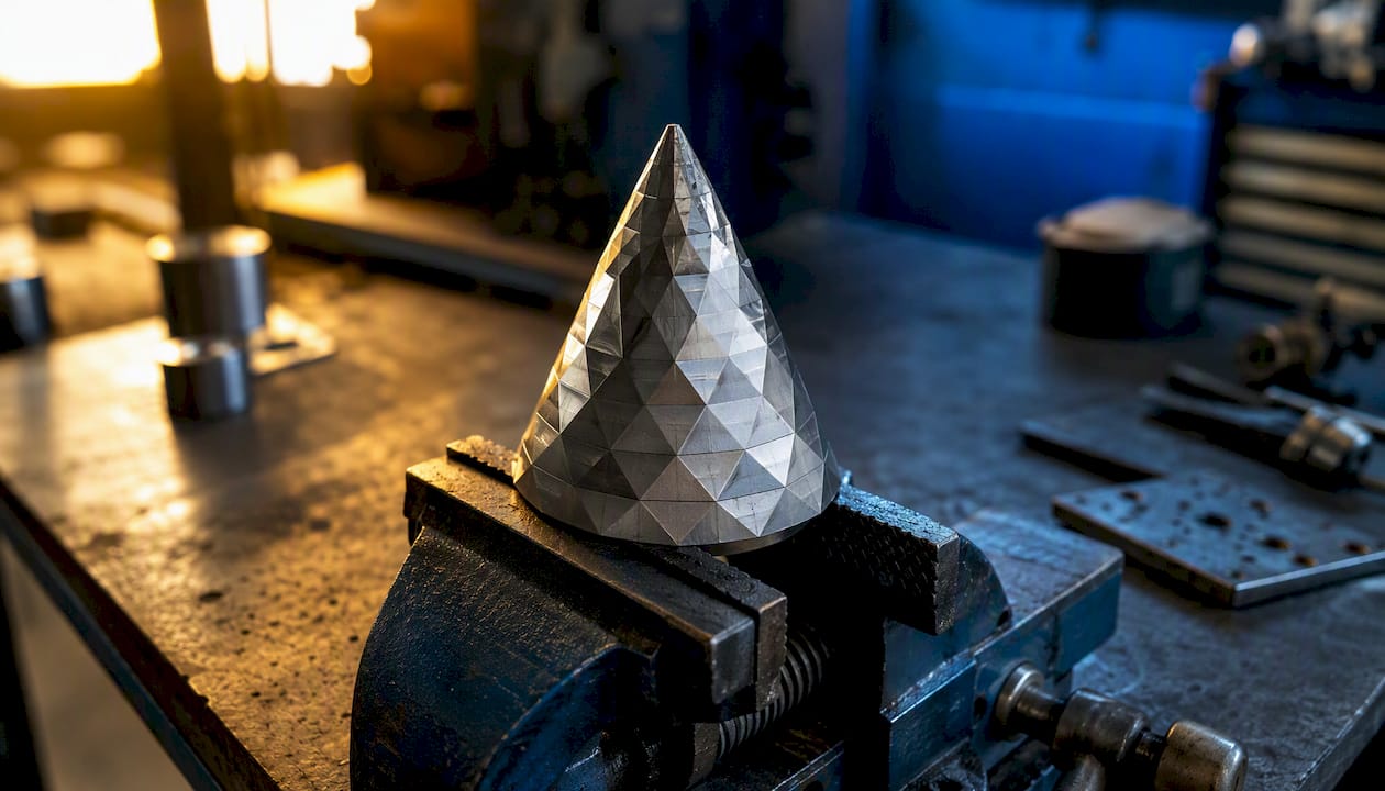
Picture a cone tessellated at a loose tolerance: you'd see maybe a dozen flat triangular facets running up its side, visibly angular. Tighten the tolerance and that same cone gets wrapped in hundreds of thinner triangles, and the facets disappear to the eye even though they're still technically there.
| Attribute | STL (mesh) | STEP (parametric/B-rep) |
|---|---|---|
| Geometry type | Triangulated facets | Exact surfaces (NURBS, B-rep) |
| Units stored | No | Yes |
| Editability | Not practically editable | Fully editable in CAD |
| Assembly support | No (single mesh) | Yes, multi-part structures |
| Typical file size on curved parts | Larger, grows with triangle count | Smaller, resolution-independent |
| Color/metadata | None | Material and metadata support |
| Tessellation setting | Effect on triangle count | Effect on surface |
|---|---|---|
| Loose chordal tolerance | Fewer triangles, smaller file | Visible faceting on curves |
| Tight chordal tolerance (0.01mm) | Many more triangles, larger file | Smooth appearance, longer slice time |
| Wide angular tolerance | Fewer triangles at edges | Sharper visible facets |
| Narrow angular tolerance (0.5°) | Denser mesh near curves | Near-seamless curve rendering |
When Should You Use STEP and When Should You Use STL?
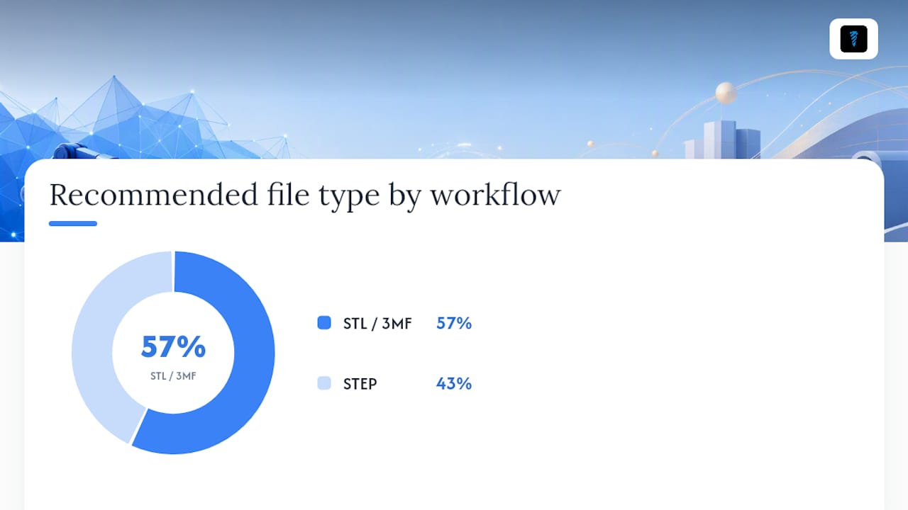
Send STEP whenever editability, tolerances, or CAM programming matter. Send STL, or 3MF where supported, when the destination is a slicer and nothing downstream needs to reopen the design in CAD.
That single distinction covers most of the confusion people run into. Here's how it plays out across specific processes:
- FDM printing. STL or 3MF works fine. Layer resolution usually swamps any faceting error from a reasonable tessellation setting.
- SLA/resin printing. Tighter tessellation matters more here since layer heights are finer and surface finish is more visible. Use a tighter chordal tolerance than you would for FDM.
- SLS and powder-based printing. Similar to SLA, small mesh errors like non-manifold edges cause more visible print defects because there's no support material masking them.
- Metal DMLS. STEP is often preferred going in, because tight tolerances and wall-thickness accuracy matter more than they do in polymer prototyping, and mesh repair work eats into expensive build time.
- CNC quoting and CAM programming. STEP, without question. A machinist needs true surfaces and exact dimensions, not a triangle approximation of them.
- Injection mold tooling. STEP again, since mold designers need to modify draft angles, add ejector pins, and adjust wall thickness directly on the model.
- Scanned or organic outputs. STL is often the only realistic option, since there was no parametric model behind the scan to begin with.
A practical checklist before you send a file anywhere:
- Confirm whether the recipient needs to edit the geometry (send STEP) or just print it (send STL/3MF)
- When in doubt, send both. A STEP master plus a print-ready STL costs you nothing and saves a round-trip email later.
- Double-check units before export. Don't assume the recipient's software defaults match yours.
- Note your tessellation settings somewhere the file will actually travel with, like the filename or a companion note.
How Do You Convert Between STEP and STL Without Breaking the Part?
STEP to STL is a one-way triangulation, and it's generally reliable as long as you control the tolerances. STL to STEP is a different animal entirely, closer to reverse engineering than conversion, and it rarely recovers the original design intent.
Going STEP to STL, you're choosing chordal tolerance and angular tolerance, and those choices set your triangle count and your file size directly. Tighter tolerance means a heavier file and a smoother result. There's no universally "correct" setting, just a right setting for the part in front of you: a decorative vase can tolerate loose tolerance, a precision-fit enclosure can't.
Going STL to STEP means fitting mathematical surfaces to an existing mesh and guessing at the design intent behind it. Some mesh-to-BREP tools can do this for simple shapes, but complex assemblies with fine features usually come out wrong or need extensive manual cleanup. Most practical guides agree that treating STL to STEP as a routine operation is a mistake. Treat it as a last resort, not a workflow.
A workflow that avoids most headaches:
- Design and hold the revision history in your CAD tool, exporting STEP as the permanent master file.
- Before exporting, run a tolerance check against the fits and clearances your design actually needs.
- Export an incremental STL each time you print, with a filename that documents the tolerance used and the version number.
- Inspect the resulting mesh for non-manifold geometry, inverted normals, and zero-area triangles before it ever reaches a slicer.
- Run a test slice, and for anything with a tight fit, print a small test-fit feature before committing to the full part.
Before sending an STL to print or to a shop, run this repair checklist: confirm units match the destination software, verify the mesh is manifold with no holes, check for inverted normals, remove features smaller than your printer's minimum wall thickness, and confirm wall thickness throughout meets your process's minimum. Several free STEP to STL converters bundle these inspection and repair steps automatically, flagging bounding box mismatches and zero-area triangles before you export.
Pro Tip: If a part has a critical press fit, run the numbers through a press-fit tolerance reference before you lock in your export tolerance. A facet that's fine for a decorative bracket can ruin a bearing bore.
Which Software Accepts STEP, Which Needs STL, and Where They Overlap
Most parametric CAD packages accept STEP natively without any conversion step. Mesh-focused sculpting tools generally expect STL or OBJ instead, and won't know what to do with a parametric feature tree even if you feed it to them.
Slicers sit in the middle. Many now accept STEP directly, but as covered earlier, they tessellate it on import rather than slicing the true surfaces. That means the mesh quality you get depends on the slicer's internal tessellation settings, not yours, unless you export the STL yourself and control chordal and angular tolerance beforehand.
CAM software for CNC work almost universally wants STEP, since toolpath generation depends on exact surface geometry, not an approximation of it.
Version differences matter more than people expect. An older CAD release might choke on a STEP file exported from a newer version using a later AP (Application Protocol) revision. If a supplier's software behaves unpredictably with your STEP export, check their exact version and export settings before assuming the file itself is broken. A CAD viewer that previews the file before it leaves your machine catches most of these mismatches early.
A Real Workflow: Keep STEP as Master, Ship STL as the Artifact
Here's how a clean handoff actually looks in practice, step by step:
- Design in CAD, keeping the feature tree intact so every dimension stays parametric and editable.
- Verify tolerances against the mating parts or assembly requirements before you export anything.
- Export STEP as the permanent master file, and store it under version control with a clear naming convention.
- Export STL at a specified tolerance for a test print, documenting the chordal and angular settings you used.
- Slice and print a test coupon, or a small reference feature, before committing material to the full part.
- Version everything, so if the test print reveals a problem, you know exactly which STEP revision and which export settings produced it.
Modern slicers like PrusaSlicer demonstrate the tessellation step directly. Load a STEP file and watch the import process convert it to a mesh in real time, which is a useful way to actually see the auto-tessellation behavior everyone talks about but few people watch happen.
Pro Tip: For anything with a critical tolerance, include a small test-fit coupon alongside the main part in the same print. It's a five-minute addition that tells you whether your tessellation settings held up before you commit the real part to material.
The Case for Never Skipping the Master File
I've seen the same failure pattern too many times to call it bad luck: someone edits an STL because it's the only file they still have, hits a wall trying to add a feature that a mesh simply can't represent cleanly, and ends up rebuilding the part from scratch. The STEP file that would have made that edit trivial got deleted months earlier because "the STL prints fine."
The conventional wisdom treats file format as a technical footnote, something you pick based on what your printer accepts. I'd argue it's closer to a data-retention decision. STEP is the only one of the two that survives a design change six months from now. STL is a snapshot, useful for exactly the print run it was made for and increasingly useless the moment the design evolves past it.
My rule of thumb, and the one I'd want any shop I worked with to follow: if there's any chance you'll revise the part, ever, keep STEP. Only export STL once the design is genuinely frozen for that specific print run. It costs nothing to keep both files. It costs real time to rebuild a model from a mesh because the source got treated as disposable.
Try the CAD Viewer Built for This Exact Workflow
Availzyemachinistpro's CAD viewer is built around the exact split this article just walked through: view your STEP file natively, then convert it to STL with export tolerance controls you set yourself, instead of leaving triangle density to whatever default a slicer picks on import.

The tool keeps your CAD documents versioned in one place, so the STEP master and every STL export you've generated from it live together instead of scattered across folders named "final" and "final_v2." That matters most when a client asks for a revision three months after the original job shipped and you need to know exactly which export settings produced the print they approved.
If you're running a small shop or managing files across a team, that document history plus role-based access means nobody accidentally overwrites the master with a triangulated copy. Start a free trial and run your next STEP-to-STL conversion through it before your next print job goes out the door.
Sources
- 3D Printing File Formats: STL vs STEP vs OBJ vs AMF — What… — Layer X
Check your own CAD software's exporter documentation before finalizing settings, since default tessellation values vary meaningfully between programs and versions.