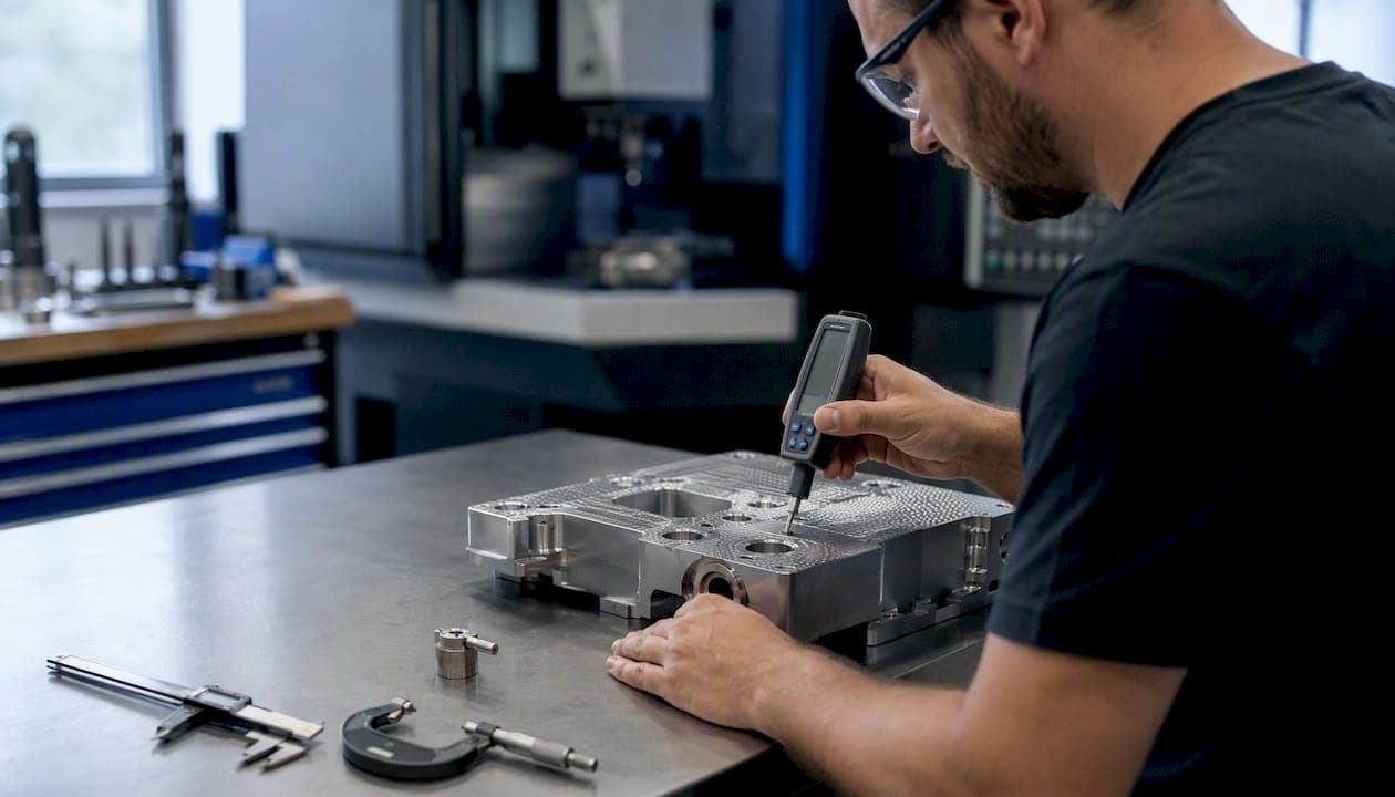
Ra measures the arithmetic average of surface deviations from a mean line. Rz measures the average of peak-to-valley heights across five consecutive sampling lengths. The one-line rule: use Ra for general production control and cost-effective inspection; specify Rz when peaks or valleys directly affect function, such as sealing surfaces, wear interfaces, or fatigue-critical fillets, based on design requirements.
One caution before going further: do not convert between them using a fixed multiplier. The workshop shorthand "Rz ≈ 4–7× Ra" is a rough approximation that varies with machining process and surface profile. If a drawing calls out Rz, measure Rz. If it calls out Ra, measure Ra. Substituting one for the other without measured data is how parts get accepted that should be rejected, and vice versa.
Key Takeaways
Ra and Rz measure fundamentally different properties of the same surface, and specifying the wrong one for a functional surface is a design error, not just a notation preference.
| Point | Details |
|---|---|
| Ra measures averages | Ra is the arithmetic mean of absolute deviations; it smooths over isolated peaks and valleys. |
| Rz measures extremes | Rz averages peak-to-valley heights across five sampling lengths; one bad zone raises the result. |
| Match parameter to failure mode | Use Rz for seals, wear surfaces, and fatigue fillets; Ra for general production texture control. |
| Rz ≈ 4–7× Ra is a rough bracket | This ratio varies with process and surface type; never use it as a pass/fail acceptance threshold. |
| Availzyemachinistpro | The surface-finish calculator handles unit conversions, Ra↔Rz approximations, and N-grade lookups with inspection records tied to the job tracker. |
Table of Contents
- What surface roughness actually means for your parts
- How Ra is calculated, measured, and where it can mislead you
- How Rz is defined, which variant you're looking at, and a worked calculation
- Ra vs Rz: how they compare across the dimensions that matter
- When to specify Ra vs Rz: matching the parameter to the failure mode
- How Ra and Rz are measured in the shop: instruments, settings, and what goes wrong
- Why converting Ra to Rz with a fixed multiplier is dangerous
- Standards and how to call out Ra and Rz on engineering drawings
- Practical shop workflow: from drawing to inspection to corrective action
- The parameter you specify is a design decision, not a formality
- Availzyemachinistpro puts surface-finish calculations and inspection records in one place
- Sources
What surface roughness actually means for your parts
Surface texture is not a single number. It breaks into three overlapping components: roughness (short-wavelength deviations from the nominal surface), waviness (longer-wavelength undulations), and lay (the dominant direction of the texture pattern). Ra and Rz both describe roughness, not waviness or lay.
Measurements come in two forms. A 2D profile scan traces a single line across the surface with a stylus or optical sensor and produces the height profile y(x) that feeds Ra and Rz calculations. A 3D areal scan covers a patch of surface and generates parameters like Sa and Sz, which provide more complete surface information for complex textures. Profile methods remain the production standard because they are fast, portable, and directly tied to ASME and ISO drawing callouts.
Units are micrometers (µm) in metric practice and microinches (µin) in inch practice. The conversion is 1 µm = 39.37 µin, so a common turned-steel Ra of 1.6 µm equals roughly 63 µin. Most North American shops see both on drawings, so knowing the conversion cold saves time at the profilometer.
Why does any of this matter functionally?
- Friction and sliding wear correlate with peak height, which Ra can understate.
- Sealing surfaces need valley depth control to prevent leak paths.
- Coating adhesion depends on both peak height (mechanical anchor) and valley depth (coating pooling).
- Fatigue life drops when surface peaks act as stress concentrators, a failure mode Rz tracks better than Ra.
How Ra is calculated, measured, and where it can mislead you
ASME B46.1 defines Ra as the arithmetic mean of the absolute deviations of the surface profile from its mean line over the evaluation length. The formula is:
Ra = (1/L) × ∫₀ᴸ |y(x)| dx
In discrete form on a profilometer, that integral becomes a sum: Ra = (1/N) × Σ|yᵢ|, where N is the number of sampled points and yᵢ is each point's deviation from the mean line.
A profilometer divides the total traverse into a series of sampling lengths (cutoff lengths, λc), typically five consecutive lengths for a standard evaluation. The instrument computes the mean line for each cutoff, calculates the absolute deviations, averages them, and reports Ra for the full evaluation length. The cutoff setting is critical: a 0.8 mm cutoff is the default for most machined surfaces in the Ra 0.1–2.0 µm range, but a finer surface may need 0.25 mm and a rougher one may need 2.5 mm. NIST height-parameter documentation provides formula excerpts and default discrimination settings that are worth bookmarking for profilometer setup.
Worked example: Suppose five sampled deviations (in µm) are: 0.8, 1.2, 0.6, 1.4, 1.0. Ra = (0.8 + 1.2 + 0.6 + 1.4 + 1.0) / 5 = 1.0 µm (39.4 µin).
Pro Tip: Ra's averaging nature is its weakness. A surface with one deep scratch and otherwise smooth texture can report the same Ra as a uniformly rough surface. If your part has a functional surface where a single defect causes failure, Ra alone will not catch it.
How Rz is defined, which variant you're looking at, and a worked calculation
ISO 21920-2 defines Rz as the mean roughness depth: the average of the maximum peak-to-valley heights measured within each of five consecutive sampling lengths. The algorithm:
- Divide the evaluation length into five equal sampling lengths.
- Within each sampling length, find the highest peak (Rp) and the deepest valley (Rv).
- Compute the peak-to-valley height for that length: Rzi = Rp + |Rv|.
- Average the five values: Rz = (Rz1 + Rz2 + Rz3 + Rz4 + Rz5) / 5.
The variants matter. The current ISO definition above is sometimes called Rz(ISO). Older drawings may reference RzJIS (Japanese Industrial Standard), which was historically defined as the average of the five highest peaks minus the five lowest valleys across the entire evaluation length, not per sampling length. Rzx or Rmax refers to the single largest peak-to-valley height across the entire trace. These are not interchangeable. A drawing that calls out "Rz" without naming the standard is ambiguous, which is exactly why the standard belongs on the callout.
Worked example: Five sampling lengths yield peak-to-valley heights of 5.2, 6.8, 4.9, 7.1, and 5.5 µm. Rz = (5.2 + 6.8 + 4.9 + 7.1 + 5.5) / 5 = 5.9 µm (232 µin).
Pro Tip: Rz is sensitive to noise, chatter marks, and isolated defects in a way Ra is not. A single chatter spike in one sampling length pulls the Rz number up noticeably. If you see Rz readings that jump between traces on the same surface, look at the profilometer trace for isolated events before rejecting the part.
Ra vs Rz: how they compare across the dimensions that matter
Keyence's surface-height quantification resource puts it plainly: Ra averages deviations and smooths over outliers, while Rz highlights extremes and is more sensitive to isolated defects. That single difference drives every application choice below.
| Dimension | Ra | Rz |
|---|---|---|
| What it measures | Arithmetic average of all absolute deviations from mean line | Average of peak-to-valley heights across five sampling lengths |
| Statistical property | Mean (smooths outliers) | Extreme-value average (amplifies peaks and valleys) |
| Sensitivity to defects | Low: isolated scratches or peaks are diluted | High: one bad sampling length raises the result |
| Typical application | General production QC, CNC turning/milling, drawing default | Seals, wear surfaces, fatigue fillets, coatings, optics |
| Governing standards | ASME B46.1, ISO 21920-2 | ISO 21920-2, ISO 4287 (historical) |
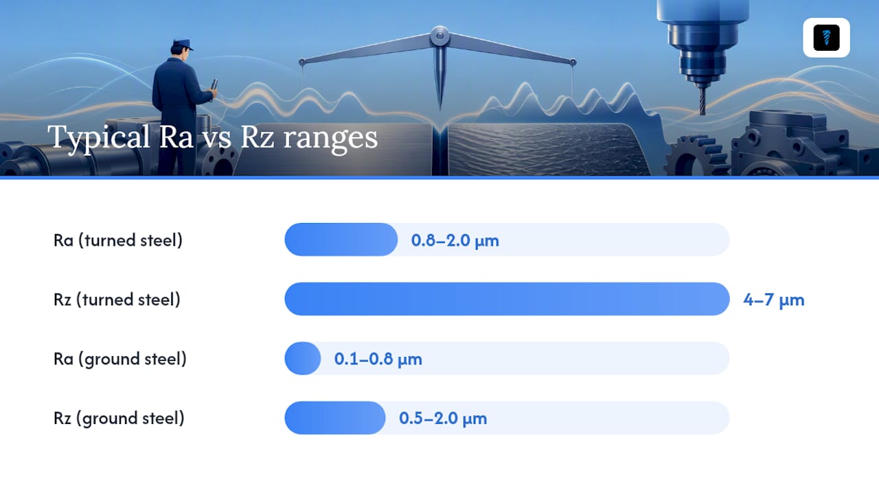
| Typical range, turned steel | 0.8–2.0 µm | 4–7 µm |
| Typical range, ground steel | 0.1–0.8 µm | 0.5–2.0 µm |
When to specify Ra:
- General machined surfaces where the primary concern is overall texture consistency.
- Production inspection where speed and cost matter and no single defect is catastrophic.
- Drawing defaults when the functional requirement is not yet defined.
When to specify Rz:
- Any surface where a single peak or valley causes functional failure.
- Sealing faces, O-ring grooves, and gasket surfaces.
- Bearing journals and sliding contacts where peak height drives wear rate.
- Fatigue-critical surfaces where stress concentrators must be controlled.
- Specify both Ra and Rz when you need average texture control AND peak/valley limits simultaneously.
When to specify Ra vs Rz: matching the parameter to the failure mode
The right parameter is the one that predicts failure. Defaulting to Ra on every surface is one of the most common specification errors in production drawings, and it costs shops rework cycles they should never have needed.
Sealing surfaces: An O-ring groove or a face seal needs valley depth control. A deep valley creates a leak path even if the average roughness looks acceptable. Specify Rz or Rzx here, not Ra alone. A typical O-ring groove face might call out Rz ≤ 6.3 µm (ISO 21920-2).

Bearing journals and wear surfaces: Peak height drives initial wear-in and long-term wear rate. Ra gives you average texture, but two surfaces with identical Ra can have very different peak heights. For press-fit and bearing surfaces, controlling Rz alongside Ra gives you both the average texture and the peak-height limit.
Fatigue-critical fillets: Surface peaks act as stress concentrators. A fillet ground to Ra 0.4 µm might still have isolated peaks that nucleate fatigue cracks. Rz or Rpk (reduced peak height) is the better parameter here.
Coating adhesion: Coatings need mechanical anchor points (peaks) but suffer if valleys are too deep (coating pools and thins at peaks). Specify both Ra for overall texture and Rz for peak/valley control.
Optics and precision reflective surfaces: Ra is the standard parameter for optical surfaces because average texture correlates with scatter. Rz is less commonly specified here unless a specific peak-height limit is needed.
Drawing callout examples:
Ra ≤ 1.6 µm (ASME B46.1)— general machined surfaceRz ≤ 6.3 µm (ISO 21920-2)— sealing faceRa ≤ 0.8 µm, Rz ≤ 4.0 µm (ISO 21920-2)— bearing journal with dual control
Common mistakes to avoid:
- Calling out Ra on a sealing surface because it is the drawing default.
- Omitting the standard from the callout, leaving the Rz variant ambiguous.
- Mixing µm and µin on the same drawing without a clear unit declaration.
- Specifying a tight Ra on a non-functional surface, driving unnecessary finishing cost.
How Ra and Rz are measured in the shop: instruments, settings, and what goes wrong
Most production shops use a portable stylus profilometer for Ra and Rz measurement. The stylus tip (typically 2 µm or 5 µm radius) traces the surface, and the instrument converts vertical displacement into a digital profile. Bench profilometers offer higher accuracy and longer traverse lengths for critical parts. Optical non-contact instruments (laser confocal, white-light interferometry) are faster and avoid stylus-tip wear but can struggle on steep slopes and highly reflective surfaces.
Key settings that must be recorded on every inspection report:
- Cutoff (λc): The spatial wavelength that separates roughness from waviness. Default 0.8 mm for most machined surfaces.
- Evaluation length: Typically 5× the cutoff (4.0 mm for a 0.8 mm cutoff).
- Traverse speed: Too fast and the stylus skips; too slow wastes time. Follow the instrument manufacturer's recommendation for the cutoff selected.
- Filter type: Gaussian filter (ISO 16610-21) is the current standard. Older instruments may use 2RC filters, which give different results on the same surface.
Inspection checklist for consistent readings:
- Clean the surface and stylus before measuring.
- Align the traverse direction perpendicular to the lay (machining direction) unless the drawing specifies otherwise.
- Run at least three traces at different locations and report the average or worst case per your quality plan.
- Verify the cutoff setting matches the drawing callout or the applicable standard default.
- Record the instrument model, stylus radius, cutoff, and evaluation length on the inspection record.
- Check the profilometer calibration status before a critical inspection run.
Pro Tip: When Rz readings vary widely between traces on the same surface, look at the raw profile trace before re-machining. A single chatter mark or tool-entry burr in one sampling length can spike Rz without the surface being generally out of spec. Identify the cause before writing a non-conformance.
Common pitfalls:
- Using the wrong cutoff inflates or deflates both Ra and Rz.
- Measuring parallel to the lay instead of perpendicular underreports roughness.
- Rz is more sensitive to stylus tip condition than Ra; a worn or contaminated tip raises Rz readings.
- Ra's averaging can mask a real defect that Rz would catch, leading to a false acceptance on a functional surface.
Why converting Ra to Rz with a fixed multiplier is dangerous
The workshop rule "Rz ≈ 4–7× Ra" is not a formula. It is an empirical observation from common machined steel surfaces, and it breaks down the moment the surface profile changes. A Springer tribology study on surface-height parameter variability found that extreme-value parameters like Rz exhibit large fluctuations between measurement areas and that Rz/Ra ratios vary widely depending on surface type and process.
Here is why the math does not hold:
- Ra is a mean of absolute deviations. It weights every point equally.
- Rz is an average of five extreme values. It weights only the peaks and valleys.
- Two profiles can have identical Ra and very different Rz values if one has occasional deep valleys and the other has uniform texture.
Worked profile example: Profile A is a uniformly turned surface with consistent peaks and valleys. Ra = 1.0 µm, Rz = 5.2 µm (ratio 5.2×). Profile B has the same Ra = 1.0 µm but includes two chatter marks that spike two of the five sampling lengths. Rz = 9.8 µm (ratio 9.8×). Same Ra, nearly double the Rz. A fixed multiplier would have accepted Profile B on a sealing surface that should have been rejected.
Practical converter tools use empirical interpolation tables and ISO lookup methods to approximate Ra↔Rz conversions, and they include explicit warnings about variability by process and material. Use them for quoting estimates only, never for acceptance decisions.
The practical recommendation:
- If the drawing specifies Ra, measure Ra and report Ra.
- If the drawing specifies Rz, measure Rz and report Rz.
- If you are writing a drawing and are unsure which to specify, add both callouts with appropriate limits.
- If you must estimate one from the other for quoting purposes, use the 4–7× range as a rough bracket, not a pass/fail threshold.
Standards and how to call out Ra and Rz on engineering drawings
Getting the callout right is not a formality. A drawing that says "Rz 6.3" without a standard reference is ambiguous because Rz under ISO 21920-2, RzJIS, and Rzx are three different numbers on the same surface.
The key standards:
- ASME B46.1: The primary North American reference for surface texture. Defines Ra, Rq, and related parameters with measurement conventions. Ra is the dominant parameter in North American practice.
- ISO 21920-2:2021: The current ISO standard for profile roughness parameters, replacing ISO 4287 for parameter definitions. Defines Rz as the mean roughness depth across five sampling lengths.
- ISO 4287/4288 (historical): Earlier ISO standards that defined Rz and measurement procedures. Many legacy drawings still reference these. Know which version a supplier is working to.
Standard-conforming drawing callouts:
Ra ≤ 1.6 µm (ASME B46.1)— unambiguous for North American suppliersRz ≤ 6.3 µm (ISO 21920-2)— unambiguous for ISO-based supply chainsRa ≤ 0.8 µm / Rz ≤ 5.0 µm (ISO 21920-2)— dual callout for critical surfaces
Drawing reviewer checklist:
- Parameter name is explicit (Ra, Rz, Rq, not just "finish").
- Standard is named in the callout or in the drawing notes block.
- Units are declared (µm or µin), not left to interpretation.
- Sampling length or N-grade is included when the default does not apply.
- All functional surfaces have their own callout; non-functional surfaces carry a general note.
For reference documentation and standards lookups, keeping a curated library on the shop floor prevents the "which Rz?" conversation from happening at the inspection stage.
Practical shop workflow: from drawing to inspection to corrective action
Turn the definitions into a repeatable process and the Ra vs Rz decision becomes fast and consistent.
Inspection workflow:
- Identify critical surfaces on the drawing and note the specified parameter (Ra, Rz, or both) and the standard.
- Select the correct cutoff for the expected roughness range (0.25 mm for fine ground, 0.8 mm for general machined, 2.5 mm for rough surfaces).
- Set the profilometer, verify calibration, and clean the surface.
- Run a minimum of three traces perpendicular to the lay at representative locations.
- Record the parameter value, instrument settings, and operator ID on the inspection record tied to the job.
- Compare against the drawing limit and document pass/fail.
A surface-finish calculator speeds the unit conversion step (µm ↔ µin), provides Ra↔Rz approximations with explicit caveats, and includes N-grade lookups so you can cross-reference ISO roughness grades (N1–N12) against Ra values without pulling out a reference chart.
Corrective action checklist for out-of-spec readings:
- Re-measure with a fresh stylus and verified calibration before escalating.
- Check the profilometer trace for isolated events (chatter, burr, tool entry mark) that may not represent the general surface.
- Inspect tooling condition: worn inserts and dull end mills are the most common source of unexpected Rz spikes. The Tool Crib inventory log and tool-life records help trace whether a tool was past its recommended life at the time of the cut.
- If the surface is genuinely out of spec, assess whether light finishing (honing, lapping, or a final light pass) brings it within tolerance.
- Document the non-conformance, the root cause, and the disposition in the job record.
Pro Tip: Log the profilometer settings alongside the measurement result in your job tracker, not just the Ra or Rz number. When a supplier dispute arises six months later, "Ra 1.4 µm" means nothing without knowing the cutoff, evaluation length, and instrument. That context is what makes an inspection record defensible.
Shop tips for reducing rework:
- Specify Ra and Rz at the quoting stage, not after the part is machined.
- Use the surface-finish calculator during quoting to verify that the specified finish is achievable with the planned process and tooling.
- Flag surfaces with tight Rz tolerances for dedicated inspection, not sampling.
- Keep measurement settings consistent across operators by documenting them in the job setup notes.
The parameter you specify is a design decision, not a formality
Most drawings default to Ra because it is the parameter machinists and engineers learned first, and because North American practice has centered on it for decades. That default is fine for a lot of surfaces. The problem is when it gets applied everywhere, including surfaces where peak height or valley depth is the actual failure mechanism.
Specifying Rz on a sealing face is not over-engineering. It is the correct engineering decision because the failure mode is a leak path created by a valley, not an average roughness that looks acceptable on paper. The same logic applies to fatigue fillets, wear surfaces, and coatings. The parameter should map to the failure mode, and that mapping should be a conscious choice made at the design stage, not an afterthought at inspection.
The conversion question comes up constantly in shops, and the honest answer is that there is no reliable conversion. The Springer tribology research on parameter variability makes this clear: extreme-value parameters fluctuate in ways that mean-value parameters do not, and the ratio between them depends on the specific surface and process. Using a fixed multiplier to accept or reject a part is a quality risk, not a shortcut.
One practical recommendation: for any part class where surface finish affects function, add both Ra and Rz to the drawing. The cost of specifying both is one extra callout. The cost of specifying the wrong one is a field failure or a rework cycle.
Availzyemachinistpro puts surface-finish calculations and inspection records in one place
Every shop eventually faces the same friction: the profilometer gives a number, the drawing calls out a different parameter, and someone has to do the conversion math on the fly while the part sits on the inspection table. Availzyemachinistpro eliminates that step.

The surface-finish calculator handles µm-to-µin conversions instantly, provides Ra↔Rz approximations with the process-dependent caveats built in, and includes an N-grade lookup table so you can cross-reference ISO roughness grades without a separate reference chart. Inspection results tie directly into the Job Tracker, so every measurement, instrument setting, and disposition is logged against the work order. When a supplier dispute or audit comes up, the record is already there. The AI Assistant can answer parameter and standard questions during quoting or inspection without pulling up a separate reference. Plans start at $9.99/month with a 7-day free trial. Start your trial at Availzye Machinist Pro.
Sources
Short list of the resources that back everything in this article:
- ISO 21920-2:2021
- Surface roughness: definition, parameters, standard methods - Polytec
- NIST VSC - Height parameters
- Springer tribology study on surface-height parameter variability