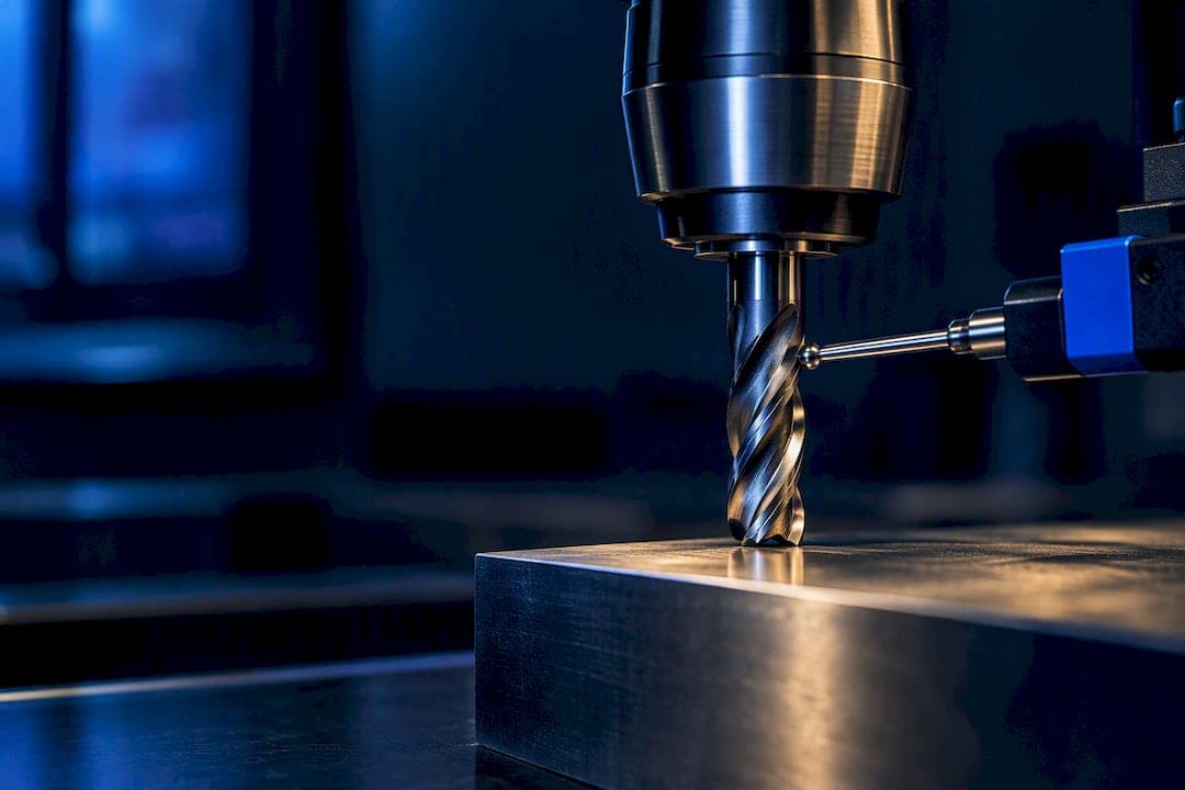
Tool deflection is the bending of a cutting tool under load, and it's the hidden culprit behind more scrapped parts than dull edges or bad programs. Before you cut, minimize unsupported stickout and run a deflection estimate or a calculator check so the bending stays inside your job's tolerance. Everything else in machining troubleshooting flows from that one habit.
TL;DR:
- Limiting tool stickout and selecting larger, stiffer tools can significantly reduce deflection and prevent dimensional errors on finished parts.
- The deflection magnitude is primarily influenced by the cube of stickout length and the fourth power of core diameter, making geometry adjustments highly effective.
- For accurate estimation, use tools like calculators or sensors during programming, and verify with measurement for critical jobs, especially on high-value or tight-tolerance parts.
- Proper toolholding and setup, including using high-quality holders and minimizing overhang, play a crucial role in maintaining rigidity.
- Most shops treat tool deflection as an after-the-fact chatter issue, but routine estimation during setup prevents scrap and improves part quality.
Table of Contents
- What Tool Deflection Is and Why It Wrecks Part Quality
- Causes and Warning Signs You Can Spot on the Floor
- The Cantilever Formula Behind Every Deflection Number
- Calculating and Measuring Deflection Before You Cut
- Practical Fixes: Tooling, Holders, and Setup Choices That Add Rigidity
- Feeds, Depth, and Direction: Tuning CAM Settings Against Deflection
- Sensor Monitoring and Where Real-Time Compensation Actually Stands
- The Two-Minute Pre-Cut Checklist
- Why Most Shops Get Deflection Backwards
- Try the Deflection Calculator Before Your Next Setup
- Sources
- FAQ
What Tool Deflection Is and Why It Wrecks Part Quality
Picture a diving board. Stand at the tip and it bows down. Stand near the base and it barely moves. A cutting tool clamped in a holder behaves the same way: the farther the tool sticks out unsupported, the more it bows away from the cut under the cutting force, then springs back when the load drops. That flex is tool deflection, and it shows up in the finished part long before anyone traces it back to the tool.
The shop consequences are concrete and expensive:
- Dimensional error: walls come out thinner or pockets shallower than programmed because the tool bowed away from the surface mid-cut.
- Poor surface finish: the tool springs back and re-engages unevenly, leaving witness marks or a wavy finish.
- Chatter: repeated flex-and-release cycles can excite vibration, turning a smooth cut into a buzzing, chipped mess.
- Shortened tool life or breakage: cyclic bending fatigues carbide and can snap a small-diameter endmill outright.
Deflection is not the same problem as runout. Runout is a rotational error, the tool wobbling off-center as it spins, usually from a bad holder or dirty taper. Deflection is a load-driven bend that happens even with a perfectly true tool. You fix runout by cleaning and reseating. You fix deflection by changing geometry, setup, or cutting parameters.
Causes and Warning Signs You Can Spot on the Floor
Deflection has a short list of usual suspects, and most jobs suffer from more than one at once:
- Excess overhang or stickout: the single biggest driver, since bending force scales sharply with unsupported length.
- Small tool diameter: thin endmills and drills flex far more readily than stout ones for the same load.
- Heavy radial or axial engagement: aggressive stepover or depth of cut multiplies the force pushing the tool sideways.
- Weak workholding or poor clamping: a part that shifts under load adds its own flex on top of the tool's.
- Tool geometry mismatches: long-flute tools with a thin core, or reduced-shank reach tools, trade rigidity for access.
On the part, deflection announces itself through tapered walls that are wider at the top than the bottom, pockets that measure undersized near the floor, a burnished or wavy finish on vertical walls, and unexplained tool wear concentrated near the tip. A quick check: run a test cut at reduced feed and see if the dimensional error shrinks proportionally. If it does, you're looking at deflection, not a program or offset problem.
The Cantilever Formula Behind Every Deflection Number
Every fluted cutting tool acts as a cantilever beam fixed at the holder and loaded near the free end, and the standard beam-deflection equation captures it well:
Δ = (F × L³) / (3 × E × I)
Where Δ is the deflection at the tip, F is the cutting force, L is the stickout length, E is the material's modulus of elasticity, and I is the area moment of inertia, which for a round tool depends on the fourth power of diameter (d⁴).
That exponent structure is the entire story of tool deflection management. Length punishes you on a cube, diameter rewards you on the fourth power. Double the stickout and deflection increases eightfold. Double the diameter and deflection drops to one sixteenth. According to the cantilever deflection breakdown at Machining Doctor, this is exactly why a modest diameter increase almost always beats a modest length reduction when you're fighting rigidity problems.
One detail trips up a lot of programmers: for long-flute endmills, the relevant diameter in that formula isn't the cutting diameter, it's the core diameter, the solid steel or carbide left after the flutes are ground. A tool advertised as a half-inch cutter might have a core closer to 0.35 inches, and that's the number that actually governs stiffness.
| Variable | Meaning | Effect on deflection |
|---|---|---|
| F | Cutting force | Direct, linear |
| L | Stickout length | Cubic (L³) |
| E | Modulus of elasticity | Inverse, linear |
| I (∝ d⁴) | Moment of inertia | Inverse, fourth power |
Turning tools bend the same way, and a 2023 study on determining actual cutting-tool deflection used the Castigliano theorem to validate that the same cantilever logic applies to lathe boring bars, not just milling cutters.
Calculating and Measuring Deflection Before You Cut
You don't need a physics degree to put a number on deflection before the spindle starts turning. The workflow most shops settle into has three tiers:
- Hand estimate: plug stickout, diameter, and an assumed cutting force into the cantilever formula for a rough sanity check.
- Calculator-assisted estimate: a feeds-and-speeds and deflection calculator does this automatically and flags when a parameter combination crosses your tolerance.
- Instrumented measurement: inductive sensors, force dynamometers, or spindle-load proxies for jobs where the calculated estimate alone isn't good enough.
Pro Tip: Run the calculator check during CAM programming, not after the first part comes off tight. Catching a marginal stepover on screen costs nothing; catching it on a scrapped titanium part costs real money.
Inductive sensors measure tip displacement directly and give the cleanest signal, but they need fixturing and calibration time that most production runs can't spare. Force dynamometers capture cutting force in real time and correlate well with predicted deflection, though they're typically a lab or toolroom instrument rather than a shop-floor fixture. Spindle-load monitoring offers a cheaper proxy, watching for load spikes that suggest excessive engagement, at the cost of less precision than direct displacement measurement.
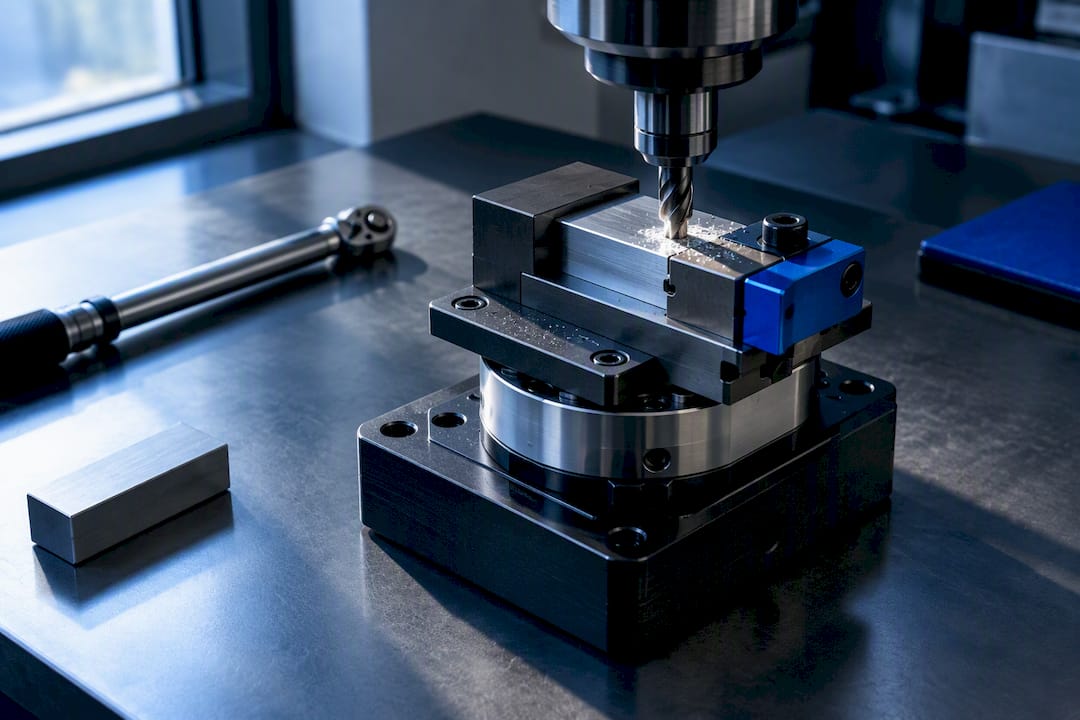
Shop guidance built around calculator tools generally treats a small deflection limit for roughing passes and an even tighter limit for finishing passes where surface finish and dimensional accuracy both matter. One worked example from CNCCookbook's deflection guide shows a 1/8 inch, 3-flute endmill with 5/8 inch stickout in 6061 aluminum limited to a small stepover just to stay within a tight deflection guideline, a far tighter number than most programmers assume until they run it.
Practical Fixes: Tooling, Holders, and Setup Choices That Add Rigidity
Reducing tool deflection comes down to attacking whichever term in the cantilever formula is hurting you most, and overhang is almost always the cheapest lever to pull.
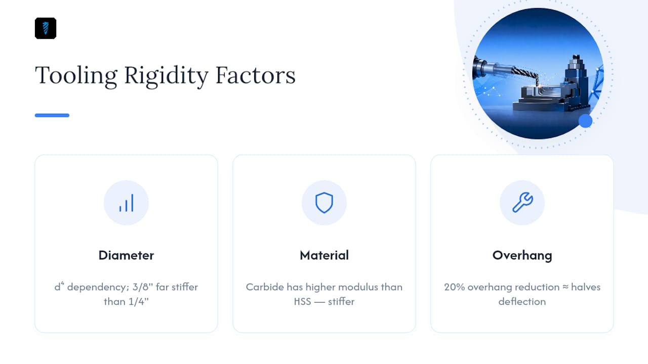
Minimize stickout first. Insert the tool only as far out of the holder as the feature actually requires. Seco Tools' guidance on short-reach setups recommends inserting the shank two to three times the shank diameter into the holder wherever the part geometry allows, and notes that cutting overhang by 20% can cut deflection roughly in half. That single adjustment often solves a chatter problem that looked like a feeds-and-speeds issue.
Favor larger diameter and stiffer material where the feature permits it. Since diameter enters the formula to the fourth power, going from a 1/4 inch to a 3/8 inch endmill buys far more rigidity than any speed or feed tweak ever will. Carbide's higher modulus of elasticity over high-speed steel adds further stiffness for the same geometry. The trade-off is obvious: small features and tight corners force you back down to small diameters, so you compensate elsewhere.
Choose long-reach versus long-flute geometry deliberately. A long-reach tool has a reduced-diameter neck behind the cutting edges purely for clearance, and it sacrifices core diameter exactly where you need stiffness. A long-flute tool keeps a fuller core along its length and holds up better under load when the application allows it. Check the actual core diameter for a given part number in a tool database rather than assuming it matches the nominal cutting diameter.
Get toolholding right before blaming the tool. Shrink-fit and quality taper holders grip more concentrically than worn collets, reducing the effective flex at the holder interface itself. Seat the collet fully, check for chips or coolant residue in the taper, and verify runout with an indicator before you chase a deflection problem that's actually a holding problem.
Feeds, Depth, and Direction: Tuning CAM Settings Against Deflection
Parameter choices at the CAM stage translate directly into cutting force, and cutting force is the F term driving every deflection calculation.
- Reduce stepover or depth of cut for small-diameter or long-stickout tools. Radial engagement multiplies side load almost linearly, so a cutter running at 40% stepover can deflect nearly double what the same cutter sees at 20%.
- Set chipload deliberately rather than defaulting to a chart value. Too light a chipload can actually increase deflection risk by promoting rubbing and heat, while too heavy a chipload spikes force directly.
- Prefer conventional milling for finishing passes on flexible setups. Climb milling generally cuts cleaner and reduces work hardening, but it can pull the tool into the cut in a way that amplifies deflection on marginal setups, making conventional milling the safer finishing choice when rigidity is already tight.
- Use high-efficiency milling (HEM) with light radial engagement and higher axial depth to keep total force manageable while still moving material quickly, rather than defaulting to a shallow, wide pass that maximizes side load.
- Take multiple light finishing passes instead of one heavy one when a wall or profile has to hold tight tolerance, letting each pass remove whatever spring-back the previous one left behind.
A high feed milling strategy guide covers how these parameter interactions play out across different cutter styles in more depth than a single checklist can capture.
Sensor Monitoring and Where Real-Time Compensation Actually Stands
Strain-gauge instrumented tool holders and dynamometer-based "feeling machine" components can measure cutting force directly during the cut and feed that signal into a compensation loop that adjusts feed rate or tool position on the fly. Research into these industrial-suited monitoring systems describes two working compensation strategies, one adjusting feed and one adjusting position, but both need careful force calibration before they're trustworthy, and both add hardware that eats into usable workspace around the spindle.
The encouraging finding across the research is consistency, not novelty. A study on high-speed milling of inclined surfaces found that inductive sensor measurements, cantilever-beam calculations, and finite element modeling all converged on nearly the same deflection values, with stepover and feed rate standing out as the two parameters that moved the needle most. That agreement matters practically:
- You don't need a strain-gauge holder to trust a cantilever estimate for routine jobs.
- Instrumented monitoring earns its cost mainly on high-value parts, exotic materials, or processes running near a tolerance edge.
- A partner overview of real-time monitoring benefits frames the same trade-off from an operations standpoint: sensing pays off fastest where downtime or scrap cost already runs high.
The Two-Minute Pre-Cut Checklist
Before the spindle starts: minimize stickout to the shortest length the feature allows, confirm the holder and collet are fully seated, size up in diameter wherever geometry permits, dial stepover down for long or slender tools, and run a deflection estimate or calculator check. Hold roughing deflection near a small limit and finishing deflection at an even tighter tolerance.
Why Most Shops Get Deflection Backwards
Most machinists treat tool deflection as a chatter problem to solve after the fact, tweaking speeds and feeds by feel until the noise stops. That's backwards. Chatter is often just deflection's audible symptom, and by the time you hear it, you've already scrapped tolerance on the part underneath it.
The bigger blind spot is diameter bias. Programmers instinctively fight deflection by slowing down, when the math says the diameter and stickout decisions made during setup matter far more than any feed rate adjustment made afterward.
What we'd push every shop toward is treating deflection estimation as a routine part of job setup, not a troubleshooting step reserved for problem parts. Log the stickout and tool selection used for a job, note whether the deflection estimate came in under the roughing or finishing threshold, and repeat that same setup next time instead of re-deriving it from memory. Availzye Machinist Pro's deflection calculator and tool database exist specifically to make that routine take seconds instead of guesswork, and a job tracker entry turns a one-time fix into a repeatable standard.
— Availzye
Try the Deflection Calculator Before Your Next Setup
Availzye Machinist Pro replaces the spreadsheet-and-memory approach most shops use for deflection with a calculator that models stickout, diameter, material, and cutting force together, then cross-checks the result against your feeds-and-speeds and chatter prediction numbers in the same session.

The tool database pulls real core diameters and geometry instead of nominal specs, so your rigidity estimate reflects the actual tool in the crib, not the catalog listing. Pair that with the job tracker to log stickout and tool choice for every setup, and a deflection check stops being a one-off calculation and becomes a repeatable step your whole team can follow. Subscription plans are available at different monthly rates for individuals and teams, and each tier includes a free trial period. Start the trial at Availzye Machinist Pro and run your next job's deflection estimate before you touch the spindle.
Sources
- Effects of tool deflection in the high-speed milling of inclined surfaces. The International Journal of Advanced Manufacturing Technology. 2004
- Calculating and Minimizing Tool Deflection for CNC Milling (CNCCookbook)
- Endmills deflection (Machining Doctor)
- Reduce tool deflection with a short reach (Seco Tools)
FAQ
How Much Tool Deflection Is Acceptable?
Shop guidance generally treats small deflection limits for roughing passes, where dimensional accuracy matters less than material removal rate. Finishing passes typically need deflection closer to very tight tolerances, since surface finish and final dimensions both depend on minimal tip movement, according to CNCCookbook's deflection calculations.
How Do You Calculate Tool Deflection?
Deflection follows the cantilever beam formula Δ = (F × L³) / (3 × E × I), where F is cutting force, L is stickout length, E is the material's modulus of elasticity, and I is the moment of inertia based on core diameter to the fourth power. Most machinists skip the manual math and run the same relationship through a deflection calculator that factors in tool material, diameter, and stickout automatically.
What Does "Deflection" Mean in Machining?
Tool deflection means the bending of a cutting tool away from its intended path under cutting force, similar to a diving board flexing under weight. It's distinct from runout, which is a rotational wobble caused by an off-center tool or holder rather than a load-driven bend.
What Tool Is Used to Measure Deflection?
Inductive sensors measure tip displacement directly and offer the most precise readings, while force dynamometers measure cutting force and let engineers back-calculate expected deflection. Spindle-load monitoring serves as a cheaper, less precise proxy, flagging load spikes that suggest excessive tool engagement, as described in research on industrial tool deflection monitoring systems.