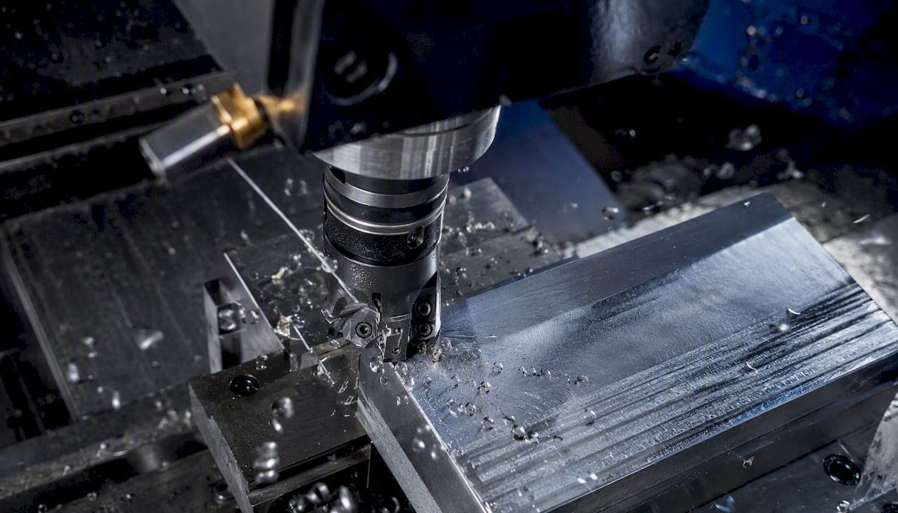
High feed milling (HFM) redirects cutting forces axially into the spindle by using a lead angle of 78°–82.5°, letting you run axial depths of 0.5–2 mm at programmed feed-per-tooth values 3–5× higher than a square-shoulder cutter on the same material. The payoff is aggressive material removal rates with surprisingly low radial force, which means longer tool overhangs, deeper cavities, and less chatter than you'd expect from those feed numbers.
Safe starting envelope for most steel applications:
- Lead angle: 78°–82.5° (tool-specific; confirm from vendor geometry data)
- Axial depth of cut (ap): 0.5–2 mm (start at 1 mm and verify spindle load)
- Radial engagement (ae): 10–40% of cutter diameter for general roughing; Sandvik Coromant recommends capping ae at roughly 20% of Dc in slicing/trochoidal contexts
- Programmed fz: 3–5× the fz you'd use with a conventional square-shoulder end mill, corrected for chip thinning (see Section 4)
- First-cut check: watch spindle load, listen for tonal shift, and inspect the chip color and shape after the first pass before committing to full-depth production
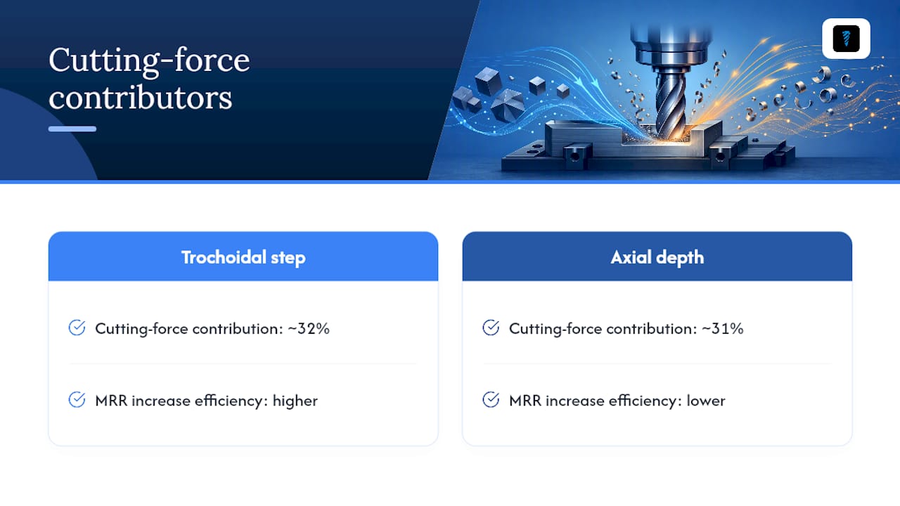
Statistic to know: In trochoidal milling research, trochoidal step accounts for roughly 32% of cutting-force variation and axial depth of cut about 31% — those two parameters are your primary force levers, not feed rate alone.
Availzye Machinist Pro's Chip Thinning and Feeds & Speeds calculators handle the fz correction math automatically, so you can enter your tool geometry and engagement and get a corrected table feed without working through the cosine relationship by hand.
Key Takeaways
High feed milling works because a 78°–82.5° lead angle redirects cutting forces axially, enabling programmed fz values 3–5× higher than conventional milling at axial depths of 0.5–2 mm.
| Point | Details |
|---|---|
| Lead angle drives force direction | A 78°–82.5° lead angle axialized cutting forces, reducing radial load and enabling long-reach stability. |
| Chip-thinning correction is mandatory | Programmed fz must be 3–5× conventional fz; always calculate from the vendor's hm value, not a standard fz reference. |
| Trochoidal step is your MRR lever | Trochoidal step accounts for ~32% of cutting-force variation; raising it increases MRR more efficiently than increasing axial depth. |
| Runout below 0.01 mm at tool tip | Unequal flute loading from runout is the leading cause of premature edge failure in multi-flute HFM tools. |
| Log every trial run | Capturing volume removed, spindle load, and insert condition in a Tool Crib log builds a shop-specific parameter database that outperforms vendor starting charts. |
Table of Contents
- How does high feed milling actually reduce radial force?
- Which cutter geometry should you choose for your operation?
- How do you calculate feeds and speeds for high feed milling?
- What CAM strategies work best for high feed milling?
- What machine and setup limits affect high feed milling performance?
- How do you troubleshoot wear and failure in high feed milling?
- Using Availzye Machinist Pro to calculate and iterate HFM parameters
- A shop-floor perspective on running your first HFM operation
- Sources
How does high feed milling actually reduce radial force?
The geometry is the whole story. A conventional square-shoulder end mill engages the workpiece at roughly 90° to the spindle axis, so most cutting force pushes radially outward. An HFM cutter's edge is ground at a steep lead angle, typically 78°–82.5°, which means the cutting edge meets the material at a shallow angle relative to the workpiece surface. The result: cutting forces are directed axially into the spindle rather than radially into the tool shank.
That force direction change is what makes long-reach HFM practical. A 4:1 or even 6:1 length-to-diameter ratio that would chatter badly with a square-shoulder cutter often runs cleanly with an HFM tool because the dominant force vector is compressive along the tool axis, not bending across it.
The chip-thinning relationship
The steep lead angle also creates chip thinning. Because the cutting edge is nearly parallel to the feed direction, the chip formed is thinner than the programmed fz would suggest. The relationship is:
hm ≈ fz × sin(lead angle)
At an 80° lead angle, sin(80°) ≈ 0.985, so chip thinning from the lead angle alone is modest. The combined correction means your programmed fz must be 3–5× higher than a conventional cutter's fz to achieve a chip thick enough to cut cleanly rather than rub and generate heat.
Standard radial chip-thinning calculators designed for conventional end mills don't fully capture HFM geometry. Tools that accept the actual edge radius or hm value and compute corrected fz based on both ae and the lead angle give more accurate results. Availzye Machinist Pro's Chip Thinning calculator handles this geometry-specific correction, which reduces the number of proof cuts needed to dial in a new operation.
Pro Tip: On the first cut, watch three things simultaneously: spindle load percentage (should stay well below rated power), chip color (straw-yellow is fine in steel; blue or black means too much heat), and the machined surface appearance (a faint scallop pattern is normal for HFM; burnishing or smearing means you're rubbing, not cutting).
Which cutter geometry should you choose for your operation?
Indexable high-feed heads vs. solid-carbide HFM end mills
Indexable high-feed cutters use replaceable inserts on a steel or carbide body. They make sense for larger diameters (typically Ø20 mm and up), high-volume roughing where insert cost-per-edge matters, and operations where you're removing a lot of material before a finish pass. The body can be reused for hundreds of hours; you swap inserts when edges dull. The tradeoff is runout: even a well-maintained indexable head carries more runout than a ground solid-carbide tool, which matters for surface finish and edge life at high feed rates.
Solid-carbide HFM end mills dominate smaller diameters (Ø6–Ø20 mm), tight-tolerance pockets, thin-wall features, and any operation where runout control is critical. They're more expensive per tool but give you tighter geometry tolerances and better surface finish. For deep-cavity work with long overhangs, the higher stiffness of a carbide shank also helps.
Practical selection rules
- Flute count: More flutes increase MRR at a given RPM but reduce chip gullet space. For aluminum and other gummy materials, 2–3 flutes prevent packing. For steel and cast iron, 4–6 flutes are common.
- Helix angle: HFM tools typically use lower helix angles (15°–30°) than high-helix finishing tools. Lower helix reduces axial pull-out forces and suits the short-engagement, high-feed cutting style.
- Core diameter: A larger core relative to outer diameter means more stiffness. For long-reach setups, choose tools with a thick core even if it means fewer flutes.
- Coolant delivery: Through-tool coolant is preferred for deep cavities and titanium. External flood works for shallow pockets in steel and aluminum where chip evacuation isn't restricted.
- Edge prep: A light hone (T-land or radius hone) protects the edge at high feed rates. Too aggressive an edge prep increases cutting forces; too sharp an edge chips at high fz values.
Manufacturer reference points
These product families are worth pulling datasheets for when selecting tooling:
- Kennametal — Mill 1–12 and HARVI HF series; strong indexable and solid-carbide HFM options with published starting parameters for steel and stainless
- Helical Solutions — HEV-5 and High Feed End Mill series; solid-carbide tools with geometry optimized for trochoidal and HFM paths
- Harvey Performance — High Feed End Mills with curved bottom-edge profiles; their published geometry data is useful for chip-thinning calculations
- Sandvik Coromant — CoroMill 210 and R390 families; extensive published parameter tables and application notes
- Seco Tools — Turbo 10 and Jabro-HFM series; good documentation on insert grade selection by material
Material-to-tool match
| Material class | Recommended cutter type | Lead angle | ap range | ae range | Starting fz multiplier vs. conventional |
|---|---|---|---|---|---|
| Low-alloy steel (P20, 4140) | Indexable or solid carbide, 4–6 flute | 78°–82° | 1–2 mm | 20–40% D | 3–4× |
| Stainless steel | Solid carbide, 4 flute, TiAlN | 78°–80° | 0.5–1.5 mm | 15–30% D | 3–4× |
| Aluminum | Solid carbide, 2–3 flute, polished | 80°–82.5° | 1–3 mm | 30–40% D | 4–5× |
| Titanium (Ti-6Al-4V) | Solid carbide, 4 flute, through-coolant | 78°–80° | 0.5–1 mm | 10–20% D | 3× |
| Cast iron | Indexable, CBN or cermet inserts | 78°–82° | 1–2 mm | 20–40% D | 3–4× |
How do you calculate feeds and speeds for high feed milling?
Core formulas
RPM = (Vc × 1,000) / (π × Dc)
Where Vc is cutting speed in m/min and Dc is cutter diameter in mm.
Table feed (Vf) = fz × Z × RPM
Where fz is programmed feed per tooth and Z is number of flutes.
The catch with HFM is that the fz you program is not the chip thickness the tool actually produces. You need to correct for both the lead angle and radial engagement. A chip-thinning feed correction is required any time ae is below half the cutter diameter, which is almost always the case in HFM.
Worked calculation example: Ø25 mm HFM cutter in 4140 steel
Given:
- Cutter: Ø25 mm, 5-flute indexable HFM, 80° lead angle
- Material: 4140 pre-hardened (~30 HRC)
- Target cutting speed: Vc = 150 m/min
- Target chip thickness (hm): 0.10 mm (from vendor datasheet)
- Radial engagement: ae = 6 mm (24% of Dc)
- Axial depth: ap = 1.5 mm
Step 1 — RPM: RPM = (150 × 1,000) / (π × 25) = 150,000 / 78.54 ≈ 1,910 RPM
Step 2 — Corrected fz from hm: For an 80° lead angle and ae = 6 mm on a Ø25 mm cutter, the chip-thinning correction factor is approximately 2.5–3.0 (geometry and engagement dependent). If the vendor specifies hm = 0.10 mm, programmed fz ≈ 0.10 × 2.8 ≈ 0.28 mm/tooth.
Step 3 — Table feed: Vf = 0.28 × 5 × 1,910 ≈ 2,674 mm/min
That's a table feed most machinists wouldn't associate with a 25 mm cutter in 4140, but it's correct when the chip-thinning correction is applied. Without the correction, you'd program something like 0.08–0.10 mm/tooth and end up rubbing the edge rather than cutting.
Key rule: Always work backward from the vendor's recommended hm (mean chip thickness), not from a conventional fz value. The programmed fz is a derived number, not a starting point.
Sample starting parameters by material
| Material | Vc (m/min) | ap (mm) | ae (% Dc) | hm (mm) | Programmed fz (Ø25 mm, 5-fl) | Vf approx. (mm/min) |
|---|---|---|---|---|---|---|
| P20 mold steel | 120–150 | 1–2 | 20–30% | 0.08–0.10 | 0.22–0.28 | 2,100–2,700 |
| 4140 (~30 HRC) | 130–150 | 1–1.5 | 20–25% | 0.08–0.10 | 0.22–0.28 | 2,100–2,700 |
| 17-4PH | 80–100 | 0.5–1 | 15–20% | 0.08–0.10 | 0.22–0.28 | 1,300–1,900 |
| aluminum | 400–500 | 1–3 | 30–40% | 0.10–0.17 | 0.28–0.35 | 5,400–8,000 |
| Ti-6Al-4V | 40–60 | 0.5–1 | 10–15% | 0.05–0.07 | 0.14–0.22 | 540–900 |
These are starting ranges. Verify against your specific tool vendor's datasheet and adjust based on measured spindle load and tool wear after the first 10–15 minutes of cutting.
What CAM strategies work best for high feed milling?
Trochoidal and constant-engagement paths
Trochoidal milling keeps radial engagement constant by programming a circular arc superimposed on a linear feed path. The key parameters are trochoidal step (the lateral advance per arc cycle) and engagement angle. Keeping both small and consistent is what gives you predictable cutting forces and long tool life.
Research confirms the leverage here: trochoidal step is the single largest contributor to cutting-force variation at roughly 32%, followed by axial depth at 31%. That means you can raise MRR more efficiently by increasing trochoidal step than by pushing axial depth, because step has a larger MRR effect relative to its force penalty. An RSM study on AISI D3 tool steel found that trochoidal step and feed rate together strongly drive surface roughness outcomes, with an optimized combination of vc = 41 m/min, vf = 210 mm/min, and trochoidal step = 0.9 mm for that specific test setup.
Helical entries and plunge tactics
Never start an HFM pass with a full-width plunge. Program a helical entry at a ramp angle of 1°–3° to bring the tool to depth gradually. For blind pockets, a center-drill or spot-drill pilot hole followed by a helical ramp is cleaner than a direct plunge. Some HFM tools are designed for plunge milling as a separate operation — check the vendor geometry before attempting it.
Corner transitions are where most HFM toolpath failures happen. A 90° inside corner forces the cutter into full-width engagement for an instant, spiking radial force and often causing chatter or edge chipping. Practitioners consistently report that smooth radiused corners and arc transitions are non-negotiable for reliable HFM. Program corner radii at least equal to the cutter radius, and use your CAM's "smooth corners" or "arc fitting" option on every inside corner.
CAM implementation checklist
- Register tool geometry correctly. Enter the theoretical cutting radius, not the nominal diameter, for HFM profiles with curved bottom edges. An incorrect radius shifts the toolpath and changes actual ae.
- Enable feed-rate correction for arcs. Most CAM packages reduce programmed feed on inside arcs (tool center moves slower than periphery). Confirm your post-processor applies this correction; without it, the actual chip load on inside arcs is higher than calculated.
- Set engagement angle limits. Cap maximum engagement angle at your target ae percentage. In Mastercam, Fusion 360, and similar packages, this is the "maximum stepover" or "engagement angle" parameter in the trochoidal or dynamic milling strategy.
- Verify trochoidal step against tool diameter. A step of 5–15% of cutter diameter is a reasonable starting range. Larger steps increase MRR but raise forces; smaller steps reduce forces but cut MRR.
- Run a full simulation before the first cut. Check for gouges, verify that corner transitions are radiused, and confirm that the tool never exceeds your ae limit anywhere in the path.
- Proof-cut in air or a sacrificial block. Confirm the programmed feed rate and spindle speed produce the expected sound and chip before committing to the actual workpiece.
Pro Tip: Before running a new HFM program on a production part, export your calculated parameters from Availzye Machinist Pro's Feeds & Speeds calculator and cross-check them against the CAM toolpath's reported chip load. If the numbers don't match, the tool geometry registration in your CAM is wrong.
What machine and setup limits affect high feed milling performance?
Spindle power and torque
HFM runs at high table feeds but relatively low cutting forces per tooth. The power draw is often moderate compared to heavy conventional roughing, but you still need to verify. Calculate required cutting power using your material's specific cutting force (kc) and the MRR you're targeting. Availzye Machinist Pro's Tool Deflection calculator and Power & Torque tool let you check whether your spindle can sustain the operation before you cut.
Torque at low RPM is the common constraint on older machines. If your spindle's torque curve drops off below 2,000 RPM, you may need to reduce Dc or Vc to stay in the machine's efficient torque band.
Runout and spindle condition
Runout is a bigger problem in HFM than in conventional milling because you're relying on every tooth carrying an equal chip load. With 5 flutes at high fz, a 0.02 mm runout means one or two flutes are doing most of the work. Measure runout at the tool tip before the first cut. For indexable heads, 0.01 mm or less is the target; for solid-carbide tools in a shrink-fit or hydraulic holder, 0.005 mm is achievable and worth pursuing.

Spindle taper condition matters too. A worn BT40 or CAT40 taper with fretting or corrosion will introduce runout and vibration that no parameter adjustment can fix. Inspect and clean the taper before any HFM setup.
Fixturing and workholding
Minimize part cantilever. A workpiece that flexes under cutting force will produce chatter even when the tool and spindle are perfectly set up. For thin-wall parts, add support fixtures or soft jaws that contact the wall. For deep-cavity work, consider a tombstone or angle plate that lets you machine from multiple sides without re-fixturing.
Statistic: Trochoidal step and axial depth together account for roughly 63% of cutting-force variation in trochoidal milling — which means your fixturing only needs to handle a fraction of the force a conventional full-width cut would generate, but it still needs to be rigid enough to prevent resonance at high feed rates.
Coolant and chip evacuation
For steel and stainless at HFM feed rates, flood coolant at adequate pressure (minimum 40–60 PSI at the nozzle) keeps chips moving out of the cut zone. Through-tool coolant is strongly preferred for deep pockets and titanium, where chip re-cutting is a common cause of premature edge failure. In aluminum, air blast or mist often outperforms flood coolant because it prevents chip welding without the thermal shock that can cause built-up edge.
Log your spindle-load baseline, tool-set runout measurement, and coolant pressure before the first cut. Capturing these in Availzye Machinist Pro's Tool Crib and Maintenance Tracker gives you a reference point for every subsequent run on that setup.
How do you troubleshoot wear and failure in high feed milling?
Common wear modes and their signals
Edge chipping shows up as a rough, torn surface finish and a sudden increase in cutting noise. The usual causes are programmed fz too low (rubbing rather than cutting), excessive runout, or a corner transition that momentarily spikes ae. Fix: verify chip-thinning correction, measure runout, and add corner radii to the toolpath.
Crater wear on the rake face indicates thermal overload. You'll see a depression forming behind the cutting edge, often with discolored chips. Reduce Vc first; if that doesn't help, check coolant delivery and consider a grade with better hot hardness (AlTiN or AlCrN coating for steel).
Built-up edge (BUE) is most common in aluminum and low-carbon steel. The chip welds to the cutting edge, increasing effective tool radius and degrading finish. Increase Vc (higher speed reduces adhesion tendency), switch to a polished flute geometry, and use through-tool coolant or air blast.
Flank wear progressing faster than expected usually means Vc is too high for the material and grade combination.
Structured troubleshooting flow
- Poor surface finish (scallops deeper than expected): Check ap — HFM always leaves scallops from the curved bottom edge; if they're too deep, reduce ap or add a light finish pass with a ball-nose or toroid cutter.
- Chatter at high feed rates: Reduce ae first (not ap), then check runout and fixturing. If chatter persists, reduce trochoidal step to lower engagement-angle variation.
- Chip packing in deep pockets: Increase coolant pressure, reduce ap, or add a chip-clearing retract move every few passes.
- Accelerated insert wear on one tooth only: Runout is the culprit. Measure and correct before continuing.
- Spindle overload at calculated parameters: Recalculate MRR and compare to spindle power rating. Either reduce ae or ap, or lower Vc.
Optimization and logging cadence
- Increase feed rate in 5–10% increments per verified run, not in large jumps.
- Log volume removed, cutting hours, and insert edge condition (photos work well) in Availzye Machinist Pro's Tool Crib after each tool change.
- After three to five tool changes on the same operation, you'll have enough data to refine the vendor's starting numbers to your specific machine, material heat, and fixturing.
- Use trochoidal step as your primary MRR lever: raising it increases MRR with a smaller force penalty than raising ap, based on the contribution percentages from the trochoidal milling research cited above.
Using Availzye Machinist Pro to calculate and iterate HFM parameters
Here's a reproducible workflow for a Ø25 mm HFM cutter in 4140 steel, using Availzye Machinist Pro from tool selection through first-cut verification.
Step-by-step workflow
Step 1 — Tool selection: Open the Tool Crib, locate or add your Ø25 mm 5-flute HFM cutter. Enter geometry: lead angle (80°), number of flutes (5), cutting diameter, and edge prep (light hone). Save the tool record so it's available for logging later.
Step 2 — Material and engagement inputs: In the Feeds & Speeds calculator, select 4140 pre-hardened as the material.
Step 3 — Chip Thinning correction: Run the Chip Thinning calculator with the tool's lead angle and the ae/Dc ratio. The calculator outputs corrected fz. For this setup, expect a corrected fz in the range of 0.25–0.30 mm/tooth, yielding a table feed of approximately 2,400–2,900 mm/min at the calculated RPM of ~1,910.
Step 4 — Deflection check: Run the Tool Deflection calculator with your overhang length and the calculated cutting force estimate. If predicted deflection exceeds 0.02 mm, shorten the overhang or reduce ap before cutting.
Step 5 — Export to CAM: Use the G-Code Generator to export the calculated RPM and feed rate into your CAM program or directly into a G-code block for verification. Cross-check the exported values against the CAM toolpath's chip-load report.
Step 7 — Log results: After the trial run, record spindle load percentage, surface finish observation, and insert condition in the Tool Crib's Tool Life log. Note the volume removed and cutting time.
Worked example summary
| Parameter | Value |
|---|---|
| Cutter | Ø25 mm, 5-flute HFM, 80° lead angle |
| Material | 4140 pre-hardened (~30 HRC) |
| Cutting speed (Vc) | 150 m/min |
| RPM | ~1,910 |
| Axial depth (ap) | 1.5 mm |
| Radial engagement (ae) | 6 mm (24% Dc) |
| Target chip thickness (hm) | 0.10 mm |
| Corrected programmed fz | ~0.28 mm/tooth |
| Table feed (Vf) | ~2,674 mm/min |
Conservative iteration cadence
If spindle load increases proportionally and surface finish holds, the parameters are stable. Never increase both fz and ae simultaneously; change one variable at a time.
A shop-floor perspective on running your first HFM operation
The first time most machinists run an HFM cutter, the programmed feed rate looks wrong. At 2,500 mm/min on a 25 mm cutter in 4140, the instinct is to back off. Don't. The physics are working in your favor: those axialized forces are going into the spindle, not into the tool shank. Trust the chip-thinning math, verify your runout, and let it run.
Watch the spindle load meter for the first 30 seconds. Inspect the insert edge under a loupe after the first pass. If the edge looks clean and the chip color is right, you're dialed in. Log everything in Availzye Machinist Pro's Tool Crib from the first run, not after you've already worn through two sets of inserts guessing at parameters. That data becomes your shop's own starting-point database, which is worth more than any vendor chart after the first dozen runs.
Sources
The following sources were used in this article. Vendor pages contain parameter tables; research papers cover trochoidal parameter effects experimentally.
- Effects of process parameters on cutting forces, material removal rate, and specific energy in trochoidal milling
- Advancedmanufacturing
- Slicing / trochoidal milling (Sandvik Coromant knowledge base)