For fast tool-break detection, monitor drive current. For protecting spindle bearings from overload, use a displacement-based sensor system. The immediate action either way: turn on and log your VFD current output at a sampling rate matched to your goal, or check the sampling specs on any in-spindle sensor already installed. Get that baseline logging right and everything else, thresholds, alarms, predictive maintenance, follows from it.
TL;DR:
- Monitoring drive current at appropriate sampling rates effectively detects tool breakage, but cannot catch micro-bearing issues that require high-frequency displacement sensors.
- Direct spindle displacement sensors offer millisecond response times and are ideal for protecting bearings in high-value, heavily loaded spindles, though they come with higher costs.
- Combining multiple signals, like current and vibration, reduces false alarms caused by transient operations such as tool entry, coolant sprays, or rapid moves.
- Setting thresholds requires validation through baseline waveforms and should be adjusted gradually, with logging to facilitate condition-based maintenance.
- Starting with low-cost drive signal monitoring and validating thresholds over a week minimizes disruption before considering high-resolution displacement systems for critical spindles.
Table of Contents
- How Spindle Load Monitoring Works: Current, Torque, and Direct Measurement
- Monitoring Hardware Options: Drive Signals, In-Spindle Sensors, and Smart Holders
- Detection Algorithms: Turning Raw Signal Into a Usable Alarm
- Setting Thresholds and Configuring Machine Reactions
- Wiring and Sampling: Getting a Clean Signal Into Your Controls
- Why Spindle Load Monitoring Throws False Positives (and How to Stop It)
- Verifying and Calibrating Your Spindle Load Monitoring Setup
- How Shop Software Turns Raw Load Data Into Maintenance Action
- Rolling Out Spindle Load Monitoring Without Disrupting Production
- A Software Path to Cleaner Spindle Load Data
- Sources
How Spindle Load Monitoring Works: Current, Torque, and Direct Measurement
Spindle motor current rises predictably with cutting load, which is why it's the default signal for spindle load monitoring on most CNC machines. It's a proxy, not a direct measurement. The motor draws more amperage as torque demand increases, and that relationship is close enough to linear for tool-break detection and gross overload alarms across most milling and turning operations.
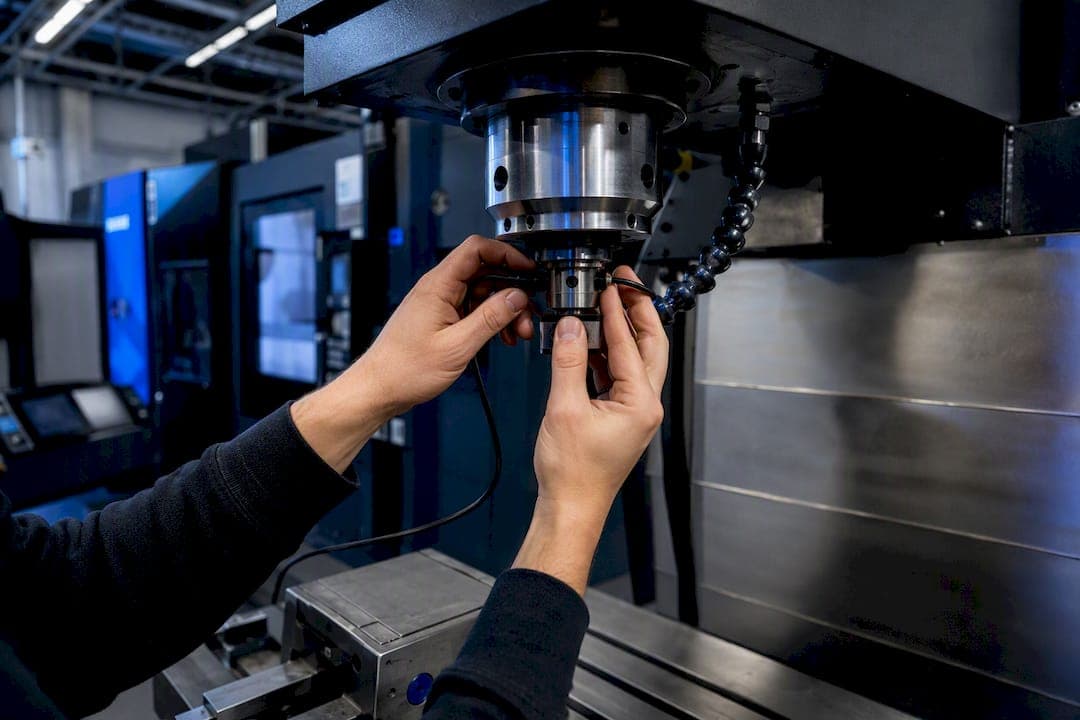
Direct displacement or deflection measurement is a different animal entirely. Sensors built into the spindle housing track actual shaft movement, in axial, radial, or tilting directions, at micrometer precision. Schaeffler's SpindleSense system, for example, can flag critical operating conditions and bearing overloads within roughly 2 milliseconds. That kind of latency isn't about catching a broken end mill. It's about catching bearing wear before it turns into a $30,000 spindle rebuild.
The gap between these two approaches shows up most clearly in sampling rate and what each one can actually see:
- Motor current/torque proxies: often sampled from the drive at rates adequate for tool-break detection, but not fast enough to catch micro-level bearing anomalies.
- In-spindle displacement systems: can sample in the kilohertz range, resolving bearing-related events in milliseconds rather than seconds.
- Rule of thumb: if your concern is broken inserts, stalled tools, or crashed programs, current monitoring is enough. If you're running high-value spindles at sustained heavy loads and bearing life is the risk, direct measurement earns its cost.
Most shops don't need both. Know which failure mode you're actually trying to catch before you spend money on hardware.
Monitoring Hardware Options: Drive Signals, In-Spindle Sensors, and Smart Holders
Three hardware paths cover almost every shop's needs, and they sit at very different points on the cost-versus-resolution curve.
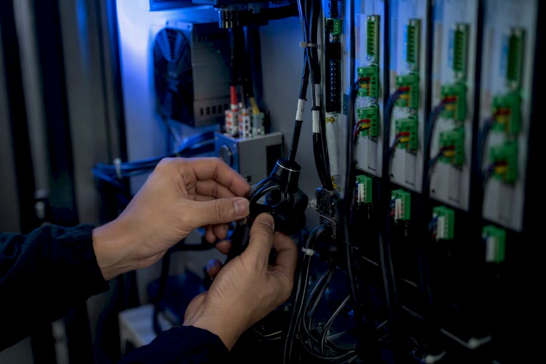
Drive-derived monitoring taps signals your VFD or servo drive already generates. Most industrial drives output a 0 to 10 V analog signal proportional to torque or current, and some expose the same data digitally through drive telemetry. Current transformers (CTs) clamped around motor leads work too, and they're often the cheapest retrofit on older machines with no drive-level analog output at all.
In-spindle integrated systems sit inside the spindle assembly itself. Pro-micron's spike® Inspindle measures bending moment, axial force, and spindle load directly, with a quoted sampling rate up to 2.5 kHz. That resolution supports near-real-time detection and, critically, automatic machine reactions, the spindle can trigger a feed hold or alarm before an operator even notices a problem. These systems typically also expose Profibus, Profinet, MQTT, or OPC UA outputs for direct integration into machine controls and plant networks.
Tool-holder and smart-holder sensors measure cutting force closer to the point of contact, which adds resolution for specific inspection or research applications, though they're less common on general production floors.
The trade-offs break down cleanly:
- Drive-derived signals: lowest cost, easiest retrofit, moderate latency, good for tool-break and crash detection.
- In-spindle sensors: highest cost, best resolution and latency, purpose-built for bearing protection and automatic machine reactions.
- Smart holders: added precision for niche force-measurement needs, but higher maintenance overhead and limited to compatible tooling.
Pick based on the failure mode you're guarding against, not on what looks most impressive on a spec sheet.
Detection Algorithms: Turning Raw Signal Into a Usable Alarm
Raw current or displacement data means nothing without a detection algorithm behind it. Four approaches dominate real shop-floor implementations, each with a distinct failure mode of its own.
- Peak detection. Fastest to implement and fastest to react, but prone to false trips from transients like tool entry, chip evacuation spikes, or coolant surges. Pair it with a short debounce window (tens of milliseconds) and a contextual filter that ignores the first few hundred milliseconds of a cut.
- Rolling average with adaptive baseline. Instead of comparing load to a fixed number, this method compares it to a moving average of recent cuts, which absorbs gradual shifts from material hardness or coolant flow without triggering nuisance alarms. Industry guidance generally favors rolling-average or energy-area comparison over pure peak monitoring specifically because it separates real process errors from expected variation. Window lengths of 0.5 to 2 seconds with frequent updates work well for most milling operations.
- Energy-area (waveform) comparison. This method integrates the load curve over the cut rather than watching a single point, which catches anomalies peak detection misses entirely, chip clogging, partial tool breakage, or gradual insert wear that raises the average without ever spiking. Waveform-based detection has direct academic backing: research on spindle motor load signals demonstrates non-contact tool-breakage detection built entirely on this kind of waveform analysis.
- Model-based and machine-learning approaches. Combining drive-based torque estimation with a finite element model of the spindle can estimate bearing loads without adding any external sensor, reconstructing cutting forces from motor torque alone and feeding them into the FEM model. This "virtual sensing" direction is where the industry is heading, but it demands more computational overhead and a larger dataset to train against than a simple threshold ever will.
Pro Tip: Don't default to peak detection just because it's the simplest to wire up. Run rolling-average and area-based detection in parallel for the first few weeks. You'll see almost immediately which one actually matches your process, and you'll avoid tuning your entire alarm system around a method that's wrong for your material mix.
As a sampling-rate baseline: tool-break detection on current signals is workable at moderate rates, but bearing-related anomalies and fast transients need 1 to 2.5 kHz sampling to avoid missing short-duration events entirely.
Setting Thresholds and Configuring Machine Reactions
A threshold that's too tight shuts down production over nothing. One that's too loose lets a broken insert run for three more parts before anyone notices. Getting it right is a process, not a guess.
Absolute thresholds work fine for stable, repeatable jobs, one material, one tool, one program, run over and over. Adaptive thresholds, tied to a rolling baseline, handle shops running mixed materials or frequent job changeovers where a fixed number would need constant re-tuning.
Once a threshold trips, the machine reaction matters as much as the detection itself:
- Feed-rate scaling: automatically reduce feed when load creeps toward the warning band, buying time before a hard stop.
- M-function triggers: custom M-codes can log an event, sound a warning, or pause the cycle without a full alarm state.
- Full alarm/stop: reserved for confirmed overload conditions where continuing risks tool, part, or spindle damage.
A practical rollout sequence looks like this: capture baseline waveforms across your normal job mix first, then raise sensitivity in small, guarded increments, validating each change against known-good production cuts before moving to the next. Skipping the validation step is the single most common reason shops abandon load monitoring within the first month, they set thresholds too aggressively, get flooded with nuisance alarms, and disable the whole system out of frustration.
Every alarm event, tripped or not, should get logged. That log is what eventually lets you move from reactive alarms to real condition-based maintenance, spotting a bearing that's trending worse over three weeks instead of finding out when it fails on a Friday afternoon.
Wiring and Sampling: Getting a Clean Signal Into Your Controls
Bad wiring produces bad data, and bad data produces alarms nobody trusts. A few installation basics prevent most of the headaches shops run into.
Getting the raw signal usually means one of three paths: tapping the VFD's 0 to 10 V analog torque output, clamping a current transformer around a motor lead, or pulling drive telemetry directly if your controller supports it. Analog taps are simple but sensitive to electrical noise on the shop floor.
- Use shielded, twisted-pair cable for any analog run longer than a few feet, and ground the shield at one end only.
- Add anti-aliasing filtering ahead of the ADC if your sampling rate is anywhere near the frequency content of the signal you're trying to catch.
- Isolate low-voltage sensor circuits from motor and VFD power wiring; shared conduit is a common source of intermittent, hard-to-diagnose noise.
- Match ADC resolution and sampling rate to your detection method: peak and rolling-average detection tolerate lower rates, waveform and bearing-protection systems need the higher end of the 1 to 2.5 kHz range.
For integration, digital alarm outputs wired straight to a PLC input are the simplest path for stop/feed-hold logic. Shops running networked monitoring increasingly lean on OPC UA or MQTT telemetry, which several in-spindle sensor systems support natively, to feed dashboards and historian software without a separate PLC integration project.
Why Spindle Load Monitoring Throws False Positives (and How to Stop It)
Every shop running load monitoring eventually gets an alarm during a perfectly good cut. Certain operations are just noisy by nature.
- Peck drilling and plunge cycles generate repeated transient spikes as the tool enters and retracts, which peak detection reads as overload events.
- Tool entry and exit on any interrupted cut spikes load for a few milliseconds, long enough to trip an undebounced alarm.
- Free-spindle operations (tool changes, air cuts, rapid moves) can register as anomalies if your baseline was captured only from loaded cuts.
- Coolant spray and material hardness variation shift the load signature enough to fool a poorly tuned absolute threshold.
Combining metrics, current plus vibration, or current plus displacement, cuts false trips dramatically because a real overload shows up across multiple signals at once, while a transient usually shows up in only one.
Pro Tip: Stage your alarms in two tiers: a warning threshold that logs an event without stopping the machine, and a hard-stop threshold set meaningfully higher. Most "false positive" complaints disappear the moment operators stop seeing every warning treated as a production-halting emergency.
Verifying and Calibrating Your Spindle Load Monitoring Setup
Skip verification and you're trusting a system you've never actually tested against a known failure.
- Capture three baseline waveforms: no-load spindle rotation, a nominal production cut, and a deliberately induced overload (a worn tool, an aggressive feed override) to see what a real fault actually looks like on your signal.
- Validate against known forces where possible. A dynamometer test isn't standard shop equipment, but if you have access to one, even briefly, it lets you correlate your current or displacement reading against an actual measured cutting force. Drive-based estimation methods validated this way have consistently identified the front bearing as the most critically loaded component in FEM-based test setups.
- Set explicit acceptance criteria: define your target detection latency and your tolerable false-positive rate before you go live, not after operators start complaining.
- Revalidate after any tooling, fixture, or program change. A new tool holder or a different workholding setup shifts your load signature enough to invalidate an old baseline.
Archive every waveform you capture. Six months from now, that library is what tells you whether a slow drift in baseline current is normal wear or an early bearing warning.
How Shop Software Turns Raw Load Data Into Maintenance Action
Detecting an overload is only half the job. What happens to that alarm afterward, whether it gets logged, correlated, and acted on, determines whether monitoring actually extends tool life or just becomes noise nobody reads.
This is where shop management software earns its place alongside the sensor hardware. Dashboards that correlate alarm history against job number, tool, and material turn a pile of individual events into a trend line. Feeds and speeds calculators and chatter prediction tools help explain why a load spike happened in the first place, often the fix isn't a tighter threshold, it's a corrected cutting parameter that was driving load too high to begin with.
Linking a detected event straight to tool-crib inventory closes the loop: a spindle-load alarm on a specific job automatically flags the tool involved, updates its usage log, and can trigger a low-stock reorder if that insert is wearing faster than expected across multiple jobs.
Rolling Out Spindle Load Monitoring Without Disrupting Production
Start with drive-derived current monitoring. It's cheap, it retrofits onto almost any VFD-driven machine, and it catches the failure mode, tool breakage, that costs shops the most scrap. Validate thresholds on one controlled part number for a full week before touching a second job. Only move to a displacement-based sensor system if bearing protection on a high-value spindle is the actual risk you're managing.
Budget one technician-day for wiring and initial threshold capture, then a week of parallel monitoring before you trust the system to stop the machine unattended. First-week priorities: log everything, tune debounce before sensitivity, and resist tightening thresholds until you've seen a full week of normal variation.
— Availzye
A Software Path to Cleaner Spindle Load Data
Sensors catch the overload. What happens next, tracing that alarm back to a tool, a job, or a maintenance window, is where most shops actually fall short, and it's the gap Availzyemachinistpro is built to close. Rather than a standalone dashboard bolted onto your monitoring hardware, it ties detected load events directly into the same system you already use to run feeds and speeds, track tool life, and schedule maintenance.

Run your feeds and speeds through the platform's calculators before you cut, and you'll often eliminate the load spikes that cause nuisance alarms in the first place, since tuned cutting parameters are the most common fix for a threshold that keeps tripping for no clear reason. When a real detection event happens, the Job Tracker lets you log it against the exact work order, and the Tool Crib module updates that tool's life record automatically so the next operator knows it's due for inspection, not another run.
Start with a 7-day free trial. Your first move: log one monitored detection event into the Job Tracker and see how quickly it connects to the tool and job history behind it.
Sources
- SpindleSense | Schaeffler Group USA Inc.
- spike® Inspindle for - pro-micron
- Combination of Finite Element Spindle Model with Drive-Based Cutting Force Estimation for Assessing Spindle Bearing Load of Machine Tools
- A tool breakage detection system using load signals of spindle motors in CNC machines