
For supplier handoff, send STEP (AP242 when 3D PMI matters, AP203 or AP214 for older CAM systems). For 2D CNC profiles and drawings, use DXF or DWG plus a PDF for read-only review. For 3D printing, export STL or 3MF. Keep native files for ongoing edits, and always verify any exported file in a neutral viewer before it leaves your building.
TL;DR:
- Use STEP AP242 for files containing 3D PMI only if the recipient's software explicitly supports full model-based definition; otherwise, send AP203 with a detailed PDF drawing.
- Confirm exported files have intact geometry and PMI by opening them in a neutral viewer and verifying dimension entities before proceeding with the handoff.
- Always include a PDF with critical tolerances and explicitly state units to prevent scale, font, or layer mismatches during 2D data exchanges.
- Generate STL or 3MF files from native CAD models for 3D printing, ensuring the mesh is watertight and scaled properly to avoid print failures.
- When sharing geometry between CAD systems, prefer kernel formats like Parasolid or ACIS if both parties use software built on the same kernel to minimize translation errors.
Table of Contents
- What Are the Core Differences Between CAD File Formats?
- Which 2D CAD Formats Should You Use, and When?
- What Are the Best Neutral 3D CAD Formats?
- STEP AP203 vs AP214: Which One Should You Send?
- How Should You Handle Mesh Formats for 3D Printing?
- When Should You Use Kernel or Native CAD Files?
- What's a Reliable Export and Verification Checklist?
- What I've Learned From Watching Format Handoffs Fail
- How Availzye Machinist Pro Fits Into Your File Workflow
- Where This Article's Standards and Guidance Come From
- Sources
- FAQ
What Are the Core Differences Between CAD File Formats?
Every CAD file falls into one of two camps: native or neutral. Native formats, like SolidWorks' .sldprt or Siemens NX's .prt, store the full feature history: sketches, extrudes, fillets, the parametric tree that lets you go back and change a hole diameter without rebuilding the part. Neutral formats strip that history away and describe geometry and metadata in a shared language no single vendor owns.
That distinction determines what survives a file transfer. A second, equally important split is B-Rep versus mesh. B-Rep (boundary representation) defines a part with exact mathematical surfaces, curves, and topology, the kind of precision CAM software and tolerance analysis depend on. Mesh geometry approximates those same surfaces with flat triangles. Fine for a 3D printer nozzle laying down plastic in 0.2mm layers, risky for a CNC toolpath expecting a true cylindrical bore.
Kernel formats sit in a middle category. Parasolid and ACIS are the mathematical engines several major CAD platforms build on internally, and when sender and receiver share one, geometry transfers with almost no fidelity loss.
Here's how the categories map to daily work:
- Design and internal edits: native files, full parametric history intact.
- Supplier handoff: neutral 3D formats like STEP, sometimes kernel formats when both sides match.
- Inspection and metrology: QIF or STEP AP242 with semantic PMI.
- 3D printing: mesh formats, STL or 3MF.
Which 2D CAD Formats Should You Use, and When?
DXF is the safer default whenever your recipient isn't running AutoCAD. It's an open, documented format that most CAM and CNC software parses without translation quirks. DWG is Autodesk's native binary format. It carries richer data (layers, styles, some 3D content) but assumes the other end owns an Autodesk license or a solid DWG-compatible reader.
PDF earns its place as the read-only companion, not the working file. Send it alongside your DXF or DWG so a shop floor operator or inspector can pull it up on a tablet with zero risk of accidental edits. DWF works similarly inside Autodesk-heavy pipelines but has largely lost ground to PDF for general review.
Three things quietly break 2D handoffs: mismatched units (inches versus millimeters), layer names that mean nothing to the receiving software, and fonts that don't exist on the other machine, which silently reflow your dimension text.
- Confirm units are explicit in the title block, not just assumed.
- Flatten or outline text where the recipient's software might substitute fonts.
- Call out critical tolerances directly on the PDF, redundantly, even if they exist in the DXF.
Pro Tip: Open every 2D export in a free neutral viewer, like a browser-based DXF viewer, before you send it. Fifteen seconds of checking catches ninety percent of layer and scaling disasters.
What Are the Best Neutral 3D CAD Formats?
STEP is the default choice for solid models and assemblies moving between CAD platforms, and for good reason: it's an ISO-standardized format (ISO 10303) built specifically to carry geometry, assembly structure, and, depending on the application protocol you export, product manufacturing information. What actually survives the trip depends entirely on which AP you pick, which is worth its own section below.
IGES predates STEP and still shows up in older supply chains and legacy toolchains. It's an ASCII-based format from the 1980s that typically stores surfaces and wireframes rather than clean, watertight solids. Import an IGES file today and you'll often need a healing or sewing step in your CAD software before the geometry behaves like a solid ready for meshing.
JT and 3D PDF solve a different problem: lightweight visualization. JT compresses assembly geometry for fast loading in review tools and PLM systems, and 3D PDF lets anyone with Adobe Reader rotate a 3D model without owning CAD software at all. Neither is built for re-machining or CAM programming. Treat them as viewing formats, not working geometry.
QIF fills the metrology gap. It's purpose-built to carry semantic PMI, dimensions, tolerances, and GD&T callouts, in a form measurement software can read directly, and it's gaining ground in advanced model-based definition workflows.
- STEP: solids, assemblies, PMI (AP-dependent). Best all-around default.
- IGES: legacy surfaces and wireframes, expect a healing step.
- JT / 3D PDF: fast visualization, not machine-readable geometry.
- QIF: inspection and metrology, semantic PMI built in.
STEP AP203 vs AP214: Which One Should You Send?
Send AP242 when you've confirmed the recipient's software can consume 3D PMI. Send AP203 when you're unsure of the recipient's toolchain, and back it with a PDF drawing calling out every tolerance. That's the practical rule, and it comes straight from how these three application protocols differ.
AP203 is the oldest of the three and carries basic solid geometry plus assembly structure, nothing more. AP214 builds on that with colors and layers, useful for automotive-style workflows where visual organization matters. AP242 merges both and adds full support for model-based definition and PMI, the actual GD&T symbols and dimensions embedded as data rather than drawing lines. AP203 and AP214 were formally withdrawn as active standards in 2014, though CAM systems still request them constantly out of habit.
Here's the trap that catches experienced engineers: a file labeled AP242 does not guarantee PMI actually made it inside. If your annotations were authored as flat 2D drawing views rather than true 3D semantic annotations (DimXpert in SolidWorks, or equivalent MBD tools in Inventor), the AP242 export can come out completely empty of PMI even though the file extension and protocol label say otherwise.
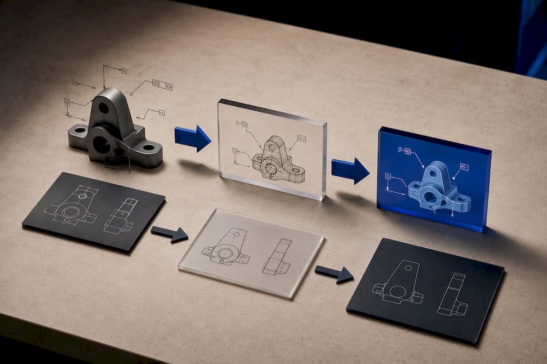
Many engineers accept whatever AP their CAD system defaults to without checking whether PMI transferred, which is exactly what causes downstream inspection setups to fail weeks after the file left the building, according to CadShift's analysis of common export mistakes.
Before you export from SolidWorks, check the swStepAP setting explicitly rather than trusting the default. In Inventor, verify the StepApplicationProtocol value, and enable "export 3D curves" and "split periodic faces" when your geometry includes cylindrical or toroidal surfaces, since skipping those flags produces gaps that only show up during CAM programming.
- Open the exported STEP in a neutral viewer and confirm the geometry looks intact.
- Check the entity list for PMI-related entities if AP242 was your target.
- Run a small round-trip test: export, reimport, compare dimensions.
- When unsure of the recipient's capability, attach a PDF drawing with tolerances spelled out.
How Should You Handle Mesh Formats for 3D Printing?
STL remains the default mesh format for 3D printing, but it's a blunt instrument: it stores triangulated surfaces with no units, no color, and no metadata, which is exactly why scale errors are so common when a file crosses between metric and imperial software. Binary STL is smaller and faster to transfer; ASCII STL is human-readable but bulky, and most production shops default to binary.
3MF fixes several STL gaps outright: it's XML-based and natively carries units, color, and multi-material information, which matters for anything beyond a single-color prototype. OBJ shows up when texture mapping matters, common in visualization and rendering rather than functional prints.
- Confirm the mesh is watertight, no gaps between triangles, before sending it anywhere.
- Check orientation and wall thickness against your printer's minimum feature size.
- Balance resolution against file size; triangle count that's too fine slows slicing for no visual benefit.
- Run a repair pass in your slicer or CAD tool if the model shows non-manifold edges.
Pro Tip: Generate meshes in-house from your STEP or native B-Rep model rather than asking a supplier to convert blind. You control the tessellation tolerance that way, and you catch scale mistakes before they become a failed print. Tools built for STEP-to-STL conversion exist precisely because this handoff breaks so often.
When Should You Use Kernel or Native CAD Files?
Parasolid (.x_t / .x_b) and ACIS (.sat) are worth requesting specifically when you know both parties run software built on the same kernel. Parasolid underpins SolidWorks and NX among others; ACIS underpins several other major platforms. A kernel-matched transfer tends to preserve geometry with fewer translation artifacts than a general-purpose neutral format, because there's no intermediate interpretation step.
Native files, .sldprt and .sldasm for SolidWorks, .ipt and .iam for Inventor, .catpart for CATIA, remain the right choice for anything you'll keep editing. Hold onto the native master, and export a neutral or kernel copy every time a file needs to leave your CAD environment for a supplier or partner.
The trade-off is real: native and kernel formats can carry vendor-specific features that simply don't translate elsewhere, and licensing terms sometimes restrict who can even open them. The practical fix most shops settle on:
- Keep the native file as your single source of truth for edits.
- Export STEP for general handoff, Parasolid or ACIS only when the kernel matches.
- When IP protection matters, share the neutral file publicly and reserve the native file for an NDA-covered exchange.
What's a Reliable Export and Verification Checklist?
Skipping verification is how a fine-looking STEP file turns into a machinist's afternoon of troubleshooting. Build this sequence into your release process instead of treating file export as an afterthought:
- Pick the format by destination. STEP for solids, DXF for 2D profiles, STL/3MF for printing.
- Set export options deliberately. Choose your AP version, decide whether colors and PMI need to travel, and don't accept software defaults blindly.
- Attach a legible PDF drawing. Call out tolerances and critical dimensions even when you believe the 3D data carries them.
- Confirm units and tolerance notes are stated explicitly, not implied by context.
- Run a geometry check in a neutral viewer before the file leaves your system.
Validating PMI presence takes one extra step: open the exported file and check whether dimension and tolerance entities actually appear in the entity list, not just the drawing view. A round-trip test, export, reimport into a second viewer, and compare dimensions, catches translation gaps before your supplier does. Enabling exporter flags like "export 3D curves" and "split periodic faces" matters most on curved or cylindrical geometry, where skipping them leaves invisible gaps that only surface once CAM software tries to generate a toolpath.
Pro Tip: Standardize one export profile per software seat across your team and document it. Individual habits, one engineer always forgets PMI, another always exports AP203 out of muscle memory, are the real source of most format failures, not the formats themselves.
What I've Learned From Watching Format Handoffs Fail
Most CAD format disasters aren't exotic. They're a missing PMI set because someone dimensioned in a 2D view instead of 3D annotations, a scale error from an unlabeled unit system, or a part that imports fine but machines wrong because a surface never got healed. The fix is almost always the same: attach a PDF, verify units explicitly, and test a small assembly before committing to a full production run.
Teams that standardize export profiles across every seat catch these problems before they ship, not after.
— Availzye
How Availzye Machinist Pro Fits Into Your File Workflow
Cloud-based software platforms offer faster ways to catch export mistakes without opening a full CAD seat every time someone needs a quick look. The CAD Viewer lets you preview incoming STEP files and convert them straight to print-ready STL, so a shop floor operator can check geometry on a machine without a CAD license tying up a workstation.

Team accounts can add role-based permissions, so an engineer can push a validated file to the shop floor while keeping edit rights locked to the design team, closing the kind of access gap that turns one bad export into a wasted production run. Pair that verification step with automated extraction workflows for manufacturing data if your team is handling PMI at scale, and the pre-send checklist from this article becomes something your software enforces instead of something everyone half-remembers.
Start a 7-day free trial and run your next STEP-to-STL conversion through the CAD Viewer before your next supplier handoff.
Where This Article's Standards and Guidance Come From
The ISO 10303 STEP standard governs the AP differences discussed above. CadShift's export breakdown covers the AP242 PMI trap in technical depth. Wevolver's CAD file guide offers broader context on format categories, and the IGES specification explains why legacy files still need healing today.
FAQ
What Is the Best CAD File Format?
There's no single best format; it depends on the task. STEP (AP242 for PMI) is the strongest default for 3D solid exchange, DXF for 2D CNC profiles, and STL or 3MF for 3D printing.
What Program Opens a CAD File?
It depends on the extension: STEP and IGES open in most major CAD platforms and free neutral viewers, DWG and DXF open in AutoCAD-compatible software, and STL opens in nearly any 3D printing slicer or mesh viewer.
What Is the Format of a CAD File?
CAD files fall into three broad formats: native (parametric, vendor-specific, like .sldprt), neutral (geometry and metadata focused, like STEP and IGES), and mesh (triangulated surfaces, like STL and 3MF).
Is a DXF File a CAD File?
Yes. DXF is a 2D neutral CAD format originally developed by Autodesk for exchanging drawing data, and it's widely supported outside Autodesk's own software, which makes it a common choice for CNC profile handoff.
Should I Send AP203 or AP242 to My Supplier?
Send AP242 only after confirming your supplier's software reads 3D PMI correctly; otherwise send AP203 with a PDF drawing calling out every tolerance to avoid the missing-PMI trap described above.