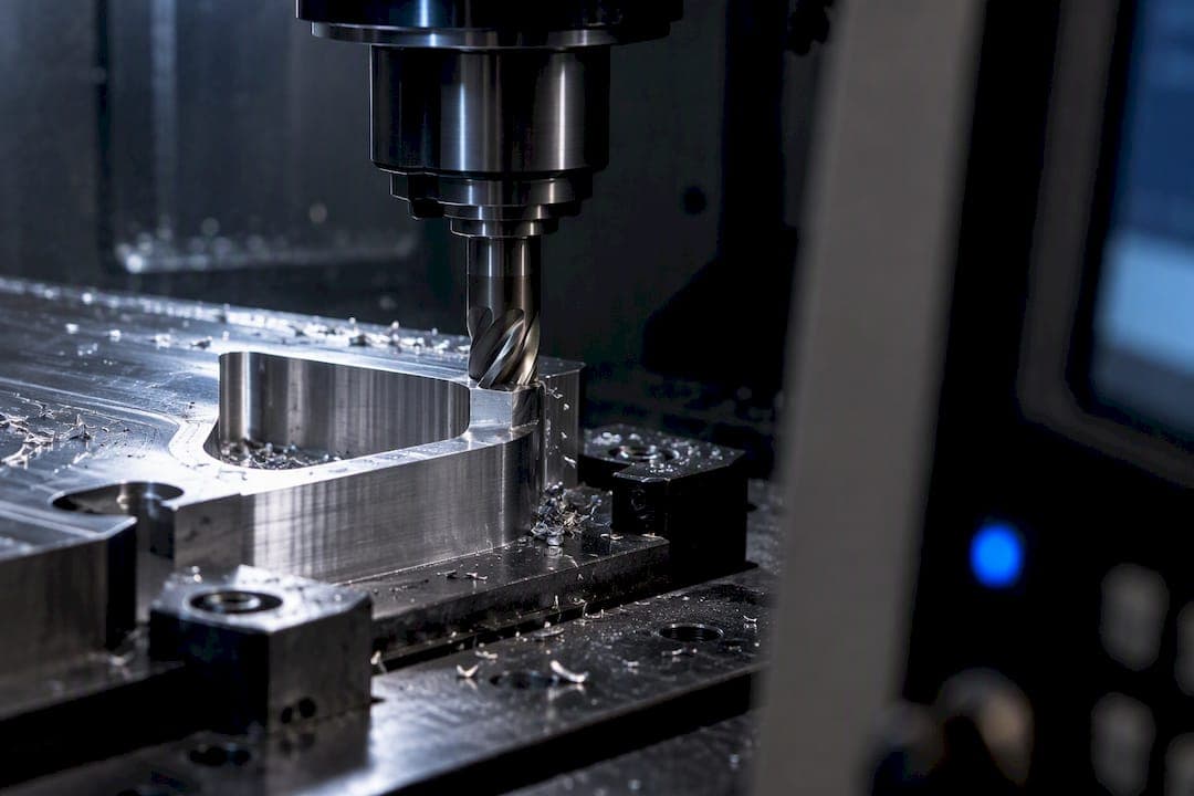
G41 shifts the tool left of the programmed path, G42 shifts it right, and G40 cancels either one. You choose left or right by standing behind the tool and looking down the feed direction: if the cutter needs to sit left of the part edge, call G41; if right, call G42. Before either code moves the machine, load a real value into the offset register and program a lead-in at least as long as the cutter radius. Skip either step and you're gouging metal, not cutting it.
TL;DR:
- Triggering G41 or G42 requires a non-zero offset value loaded into the controller; zero offsets cause unintentional nominal-sized parts despite compensation commands.
- The lead-in move must be at least the cutter radius to avoid gouging, with arc-based entries generally providing better tangency and predictable scaling.
- Proper sequence involves loading the tool, confirming the offset, engaging compensation with G41 or G42, then canceling with G40 before retracting.
- Incorrect quadrant or missing plane selection commands often lead to controller errors in cutter compensation, especially on Siemens or Fanuc controls.
- CAM-based offsets are preferable for complex profiles with tight internal corners or fillets close to the tool radius, as they incorporate full geometry rather than block-by-block adjustments.
Table of Contents
- What Is Cutter Compensation G41 and G42?
- How Do Controllers Accept Cutter Compensation Offsets?
- How Long Should the Lead-In Move Be Before Engaging Compensation?
- How Does Tool Nose Radius Compensation Work on a Lathe?
- A Worked Example: Safe G41/G42 Programming Sequence
- Why Do Some Controllers Throw Compensation Errors?
- When Should You Use CAM Offsets Instead of Controller CRC?
- Author perspective: pragmatic rules every shop should adopt
- How Availzye Machinist Pro Helps You Validate Compensation Before You Cut
- Sources
- FAQ
What Is Cutter Compensation G41 and G42?
Cutter compensation, also called cutter radius compensation (CRC) or tool radius compensation, lets you program the part's actual geometry instead of calculating an offset path by hand. The controller shifts the tool centerline away from your programmed line by whatever value sits in the offset register, so the edge of the tool, not its center, tracks the part outline.
Direction comes down to one visual check: stand behind the tool, look in the direction of travel, and see which side of the line the cutter belongs on. Left of that line is G41 = cutter compensation left; right is G42. This ties directly into climb versus conventional milling. In climb milling, the cutter rotates into the direction of feed, which usually calls for a specific compensation side to keep chip load consistent and reduce tool deflection. Conventional milling reverses that relationship.
Compensated moves also behave differently depending on the corner type:
- Outside corners get an extra arc or extended move so the tool doesn't leave a flat spot at the vertex.
- Inside corners require the tool to stop short of the intersection point, since a rounded cutter physically cannot reach a sharp internal corner.
- Tight internal corners smaller than the tool radius will trigger a controller alarm rather than silently cutting the wrong shape.
How Do Controllers Accept Cutter Compensation Offsets?
Every control reads the offset value differently, but the mechanics reduce to three methods you'll run into across most shops.
- D-register (tool table). This is the standard on Fanuc, Siemens, and Haas machines. You store a radius or diameter value in a tool table row, then call it with something like
G41 D05, where D05 points at register five. Haas documentation confirms the D-address selects the offset register directly, and a negative value in that register flips the compensation to behave like the opposite code, left becomes right and vice versa, without touching the G41/G42 call itself. - P or X inline values. Simpler routers, desktop CNC controllers, and some hobbyist-grade firmware skip the tool table entirely. You pass the radius straight into the line, as in
G42 P5.0orG42 X5.0, which is faster to set up but harder to audit across a job history. - Runtime changes with G10. You can rewrite a tool table entry mid-program using G10, useful for wear compensation, but it also means a stale G10 line from a previous job can silently apply the wrong offset to your next part.
If the register value is zero, the controller applies no compensation at all, even with G41 or G42 active, which is a common cause of parts coming out to nominal size when they shouldn't.
How Long Should the Lead-In Move Be Before Engaging Compensation?
The rule is fixed: the entry move must be at least the cutter radius, and LinuxCNC's documentation is explicit that compensated moves are calculated locally, block to block, not against the whole part geometry. A rapid approach positioned above the part, followed by a straight or arc move into the first cut, satisfies that minimum in most cases.
Arc lead-ins tend to outperform straight radial leads. Practitioners on CNC forums report that arc entries reduce tangency errors that show up when a straight lead meets a curved wall at an awkward angle, and arcs scale more predictably as you swap tool diameters without reprogramming the entire entry move.
The bigger risk sits with tight internal fillets. Controller compensation isn't aware of the whole part, just the current and next block, so a tool whose radius approaches or exceeds a fillet radius can gouge material the programmer never intended to remove.
- Check every internal radius against your largest roughing tool before you cut air.
- Stage roughing passes with a smaller effective diameter, then finish with the true tool.
- Run the program through CAM tool path simulation before it ever touches a vise.
Pro Tip: Don't trust a dry run on the machine screen alone. A full CAM simulation catches compensation-related gouges that a simple G-code viewer will miss, especially on profiles with mixed inside and outside corners.
How Does Tool Nose Radius Compensation Work on a Lathe?
Lathe work uses a related but distinct system: tool nose radius compensation, sometimes shortened to TNRC. Instead of a single cutter radius, the controller reads a nose radius value paired with a tool orientation, or quadrant, number that tells it which direction the nose curves relative to the tool holder.
Getting the quadrant wrong is the single most common lathe CRC mistake. The controller needs to know whether the tool nose faces up, down, or to a specific side to calculate the correct offset direction, and a wrong quadrant setting produces an offset that's mirrored or simply absent.
- Set tool orientation before you ever cut a taper or a profile, not after the first part comes out wrong.
- Facing operations often expose quadrant errors first, since the nose radius has the most visible effect on a flat face.
- Internal boring profiles are especially sensitive because there's no room to recover from an offset in the wrong direction.
A Worked Example: Safe G41/G42 Programming Sequence
Here's a straightforward milling sequence that follows the correct order: call the tool, confirm the offset, engage compensation with a lead-in, cut, then cancel.
Sequence logic: load tool and offset first, position above the part, engage compensation only as you move into the cut, and always return to G40 before retracting. Reversing any of these steps is how machinists gouge parts they've run successfully a dozen times before.
T01 M06 (load tool 1)
G43 H01 (apply tool length offset)
G00 X0 Y0 (rapid to start position)
G41 D01 (activate cutter compensation left, offset register 1)
G01 X1.0 Y0 F20.0 (lead-in move, at least cutter radius long)
G01 X1.0 Y2.0 (compensated cut along part profile)
G01 X0 Y2.0
G40 G00 X0 Y0 (cancel compensation, retract)
Swap D01 for P0.25 or X0.25 if your control uses inline offset values instead of a tool table, the sequence logic doesn't change, only where the radius value lives. The critical detail is placing G40 on its own retract move, away from the finished surface, so the controller isn't canceling compensation mid-cut.

Why Do Some Controllers Throw Compensation Errors?
Different controls fail differently, and knowing the pattern saves you a service call. LinuxCNC users have reported input-path errors during compensated moves that often trace back to a missing auxiliary move between two compensated blocks, adding a short linking move or switching to an arc lead-in typically clears it.
- "Tool radius not less than arc radius" means your cutter is too large for the internal arc you're trying to cut. Swap to a smaller tool or redesign the fillet.
- Empty block or axis-selection errors, common in Siemens support forum threads, usually point to a missing plane selection command (G17/G18/G19) before G41 or G42 activates.
- Silent zero-offset cuts happen when the D-register points at an empty or zero tool table row, no alarm, just a part machined to nominal size.
When a profile keeps tripping alarms regardless of lead-in adjustments, that's the signal to shift the compensation work into CAM rather than fighting the controller's local block logic.
When Should You Use CAM Offsets Instead of Controller CRC?
Controller-based CRC is fast for straightforward profiles and field adjustments, but it isn't geometrically aware beyond the current and next block. For complex, tight-tolerance profiles with internal fillets close to your tool radius, CAM-generated compensated paths carry the whole part geometry into the calculation, not just two blocks at a time.
- Use CAM compensation when fillet radii approach your tool radius or when the profile has mixed convex and concave sections back to back.
- Use controller CRC for quick field adjustments, wear compensation, and straightforward finishing passes where setup speed matters more than geometric complexity.
- Try the nominal-zero tool-table trick: set the table diameter to zero for CAM-driven roughing, then apply the true offset only for the final finishing pass. It keeps rough and finish logic separate and easier to audit.
A tool database that tracks nominal versus actual diameters, paired with G-code analysis that flags a lead-in shorter than the tool radius before the program ever reaches the machine, catches most of these errors on the screen instead of in the vise.
Author perspective: pragmatic rules every shop should adopt
The shops that avoid compensation-related scrap don't have better machinists, they have better habits. Run a dry simulation every time, log tool offsets somewhere permanent instead of trusting memory, and drill lead-in minimums into new operators before they touch a live spindle. Use CAM for anything with tight internal geometry; let controller CRC handle field tweaks and finishing where setup speed matters more. Most compensation rework traces back to one skipped step, not a knowledge gap.
— Availzye
How Availzye Machinist Pro Helps You Validate Compensation Before You Cut
Availzye Machinist Pro is built for the exact failure points covered above: a wrong D-register, a lead-in shorter than the cutter radius, a tool table entry nobody double-checked. Instead of juggling a spreadsheet for tool offsets and a separate viewer for G-code, everything lives in one cloud-synced application you can pull up from the shop floor or the office.

The platform's G-code generator checks your program structure before it hits the machine, while the tool database keeps nominal and actual diameters straight across every job so a stale offset doesn't sneak into a new part. Pair that with the Job Tracker for logging which offsets ran on which work order, and you've got a documented trail instead of a guess. Availzye Machinist Pro runs three plans: Individual at $9.99 CAD per month, Small Shop at $24.99 CAD per month, and Team at $49.99 CAD per month, each with a 7-day free trial. Start the trial and run your next compensated profile through the G-code tools before it ever touches a vise.
Sources
- Tool Shape Compensation — LinuxCNC documentation
- G41 and G42 cutter compensation — GCodeTutor
- G41 / G42 cutter compensation — Haas technical documentation
- Radius compensation G40/41/42 milling issues — Siemens support forum
FAQ
What G-code cancels cutter compensation?
G40 cancels cutter compensation, returning the tool to its programmed centerline path. Vendor documentation, including Tormach's cutter compensation reference, recommends always ending a compensated section with G40 before retracting to avoid unintentionally running with compensation active.
What does cutter compensation mean?
Cutter compensation shifts the programmed tool path left or right by the cutter's radius, so the tool's edge, rather than its center, follows the part's actual profile. It removes the need to hand-calculate an offset path for every tool diameter you might run.
What is the difference between cutter compensation left and right?
G41 is cutter compensation left, meaning the tool shifts to the left of the programmed path when you look down the feed direction, and G42 is right. The correct choice depends on which side of the line the cutter needs to sit to cut the intended profile, and on climb versus conventional milling requirements for that operation.
What does G42 mean in G-code?
G42 activates cutter compensation right, shifting the tool to the right of the programmed line relative to the feed direction. It requires a loaded offset value, either through a D-register, tool table, or an inline P or X value, before the compensated move begins.