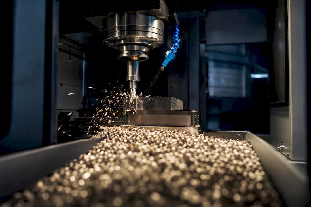
MRR (material removal rate) is volume removed per unit time, and the milling form is MRR = ap × ae × Vf, returning cubic centimeters per minute (cm³/min) in metric or cubic inches per minute (in³/min) in imperial. Here ap is axial depth of cut, ae is radial depth of cut, and Vf is table feed rate. Turning, drilling, and grinding each swap in their own geometry, but the output is always volume over time.
TL;DR:
- Using the milling formula, a table feed of 900 mm/min with 4 mm axial and 8 mm radial depths yields a material removal rate of approximately 28.8 cm³/min, or 1.76 in³/min in imperial units.
- Grinding with a 25 mm wide wheel moving at 6,000 mm/min and 0.05 mm depth achieves an approximate MRR of 7,500 mm³/min; actual removal often requires tracking weight loss instead of volume.
- Be cautious of unit mismatches, as mixing metric and imperial inputs can inflate MRR calculations by 5 to 10 times, risking spindle overload or tool failure.
Table of Contents
- What Is the Material Removal Rate Formula for Each Operation?
- How Do You Apply These Formulas With Real Numbers?
- What Unit Mistakes Wreck Your MRR Numbers?
- How Do You Check MRR Against Available Spindle Power?
- How Do You Run These Numbers Through a Calculator?
- What Do ap, ae, Vf, and Other MRR Variables Mean?
- Applying MRR on the Shop Floor
- Run Every MRR Check Without Leaving Your Shop Sheet, leveraging advanced tools like CNC Routing London | Precision CNC Cutting & Bespoke Services for practical CNC routing insights that align with your MRR calculations.
- Where These Formulas and Constants Come From
- Sources
- FAQ
What Is the Material Removal Rate Formula for Each Operation?
Every operation reduces to the same idea: cross-sectional area times feed speed. The variables just change shape.
- Milling: MRR = ap × ae × Vf → cm³/min (metric) or in³/min (imperial), where Vf is table feed, not per-tooth feed.
- Turning: MRR = DOC × f × Vc × 1000 (or DOC × f × π × D × RPM for a diameter-based build) → cm³/min, using depth of cut, feed per revolution, and cutting speed.
- Drilling: MRR = (D² × f × N) / 4 → mm³/min or in³/min, where D is drill diameter, f is feed per revolution, and N is RPM.
- Grooving: Treated like turning with a narrower DOC band. Same formula, tighter tolerance on chip evacuation.
- Grinding: MRR ≈ width × depth × table speed, but it's an approximation. Wheel wear and dressing frequency shift real removal volume, so treat the grinding number as directional, not exact, per Omni Calculator's process breakdown.
Metric numbers convert to imperial by dividing cm³/min by 16.387 to get in³/min. Keep that factor handy. It's the one most spreadsheets get wrong when someone pastes in mixed units.
How Do You Apply These Formulas With Real Numbers?
Formulas mean nothing until you run them against numbers you'd actually see on a router sheet. Here's each operation worked start to finish.
- Milling. Axial depth ap = 4 mm, radial depth ae = 8 mm, table feed Vf = 900 mm/min. MRR = 4 × 8 × 900 = 28,800 mm³/min = 28.8 cm³/min, matching the FM Carbide reference example. Convert to imperial: 28.8 ÷ 16.387 ≈ 1.76 in³/min.
- Turning. Depth of cut = 2 mm, feed per rev f = 0.3 mm/rev, cutting speed Vc = 150 m/min. MRR = DOC × f × Vc × 1000 = 2 × 0.3 × 150 × 1000 = 90,000 mm³/min = 90 cm³/min. The Iowa turning equations derive this same relationship straight from feed, DOC, and spindle speed.
- Drilling. Drill diameter D = 10 mm, feed f = 0.15 mm/rev, RPM N = 1,200. MRR = (10² × 0.15 × 1,200) / 4 = 4,500 mm³/min = 4.5 cm³/min. In imperial, a 3/8 inch drill at 0.006 IPR and 1,000 RPM gives roughly 0.66 in³/min.
- Grinding/EDM. A wheel 25 mm wide, 0.05 mm deep, moving at 6,000 mm/min gives MRR ≈ 25 × 0.05 × 6,000 = 7,500 mm³/min. Because wheel bond and dressing cycles change actual stock removal, EDM and precision grinding shops often track weight-loss-per-hour instead of volume, since that number holds up better across a shift.
Quick check: if your calculated MRR looks 5 to 10 times higher than your last known-good job, you almost certainly used per-tooth feed where the formula wanted table feed, or plugged in diameter where the formula wanted radius. Confirm units before you trust the output.
What Unit Mistakes Wreck Your MRR Numbers?
Most bad MRR calculations aren't formula errors. They're unit mismatches hiding behind a correct-looking number. A few definitions first:
- Vf (feed velocity) is the table's linear travel rate, typically mm/min or in/min.
- f (feed per revolution, IPR) applies to turning and drilling, where the tool advances a fixed distance per spindle turn.
- IPM is inches per minute; convert to IPR by dividing by RPM.
- SFM/Vc (surface feet per minute or cutting speed in meters/minute) describes tool surface speed, not feed, and it's a separate variable entirely from feed rate.
Conversion factors worth memorizing: 1 mm = 0.0394 in, 1 mm³ = 0.0000610 in³, and cm³/min ÷ 16.387 = in³/min. A 500 mm/min table feed is about 19.7 in/min. Get that backward once on a shop floor and you'll either starve the cut or stall the spindle.
Common mistakes, in order of frequency: mixing metric and imperial mid-calculation, feeding per-tooth values into a formula that expects table feed, and ignoring chip thinning on light radial engagements, which silently inflates your effective feed per tooth.
Pro Tip: Before trusting any MRR output, run a sanity check: does the number roughly match your last successful job at similar depth and feed? If it's off by an order of magnitude, recheck your unit inputs before touching the machine.

How Do You Check MRR Against Available Spindle Power?
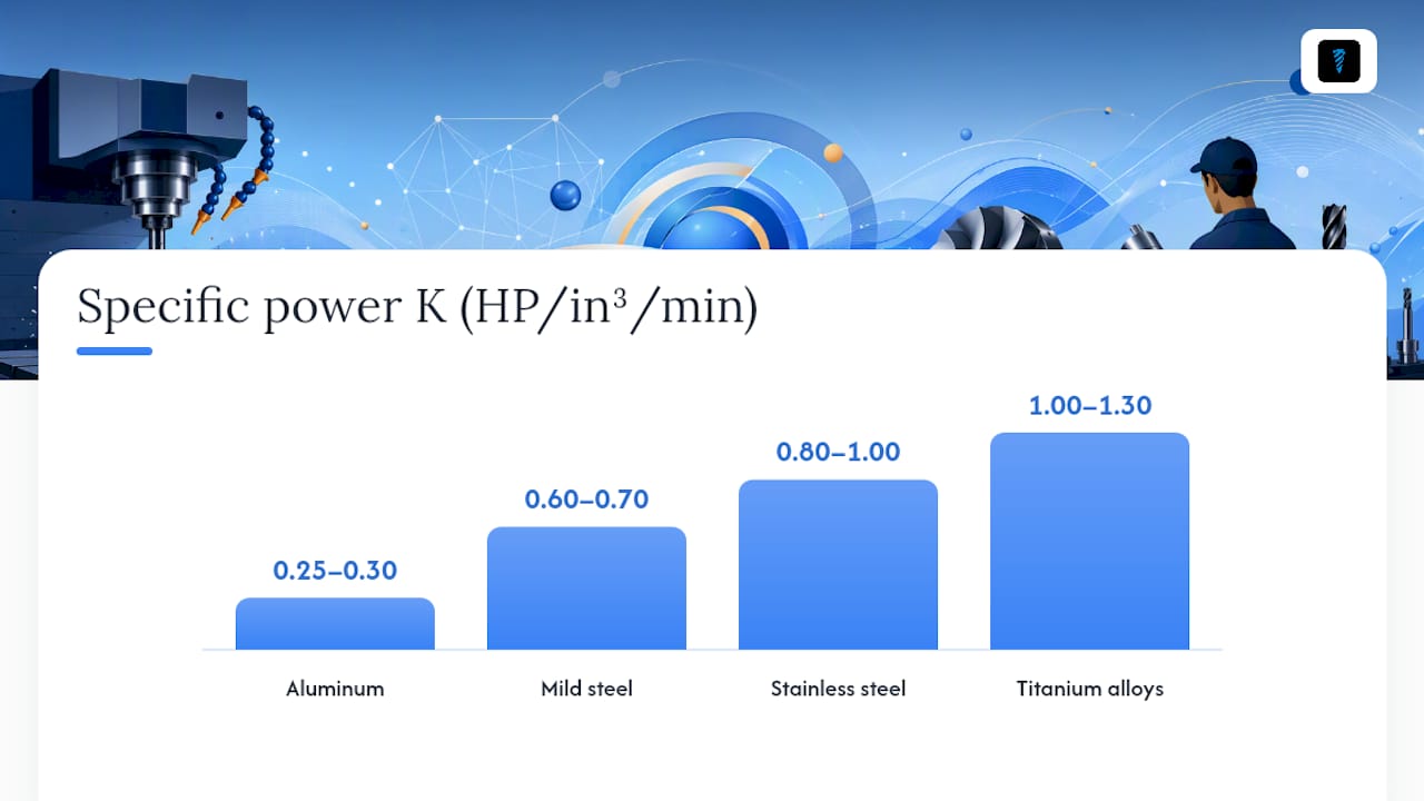
A theoretically correct MRR still stalls your machine if the spindle can't supply the horsepower to sustain it. The relation is straightforward: HP_spindle = MRR × K, where K is the specific power factor for the material you're cutting, expressed in HP per in³/min. Divide that spindle horsepower by drive efficiency (typically 0.80 to 0.90) to get required motor horsepower, a relationship the TWC Industrial calculator uses directly.
K varies by material because harder, tougher alloys demand more energy per unit volume removed.
| Material | Approximate K (HP/in³/min) |
|---|---|
| Aluminum | 0.25 to 0.3 |
| Mild steel | 0.6 to 0.7 |
| Stainless steel | 0.8 to 1.0 |
| Titanium alloys | 1.0 to 1.3 |
Example: cutting mild steel at 1.76 in³/min with K = 0.65 gives HP_spindle = 1.76 × 0.65 ≈ 1.14 HP. Compare that against your machine's continuous rated power, not the peak or intermittent figure on the nameplate. A machine that shows 3 HP intermittent might only sustain 1.5 HP continuously, and that's the number that matters on a long roughing pass.
How Do You Run These Numbers Through a Calculator?
A calculator or shop spreadsheet only saves time if you feed it inputs in the right order and catch mistakes before they hit the spindle.
- Enter operation type first (milling, turning, drilling, grinding). This sets which formula runs.
- Enter ap and ae for milling, or DOC and feed per rev for turning, confirming units match the calculator's expected input (mm vs. inch).
- Enter Vf or RPM depending on operation. Double-check whether the field wants table feed or per-tooth feed.
- Read the MRR output and convert if your CAM system or drawing uses a different unit system.
- Cross-check against HP_spindle = MRR × K to confirm your machine can hold the cut.
Worked problem: Milling 6061 aluminum, ap = 5 mm, ae = 10 mm, Vf = 1,200 mm/min. MRR = 5 × 10 × 1,200 = 60,000 mm³/min = 60 cm³/min, or about 3.66 in³/min. At K = 0.28 for aluminum, HP_spindle ≈ 1.02 HP, comfortably inside most 3-axis mills' continuous rating.
A spreadsheet formula for this is just =ap*ae*Vf/1000 to get cm³/min directly from millimeter inputs.
| Input | Value |
|---|---|
| ap (axial depth) | 5 mm |
| ae (radial depth) | 10 mm |
| Vf (table feed) | 1,200 mm/min |
| MRR result | 60 cm³/min (3.66 in³/min) |
Once you have MRR, divide programmed stock volume by MRR to sanity-check cycle time against your CAM software's estimate. If your calculator suggests a faster feed, verify it against the feeds and speeds guide before committing it to a production run.
What Do ap, ae, Vf, and Other MRR Variables Mean?
Shop paperwork and CAM software don't always use the same labels for the same values, which causes more confusion than the math itself.
- ap — axial depth of cut (mm or in), the depth the tool cuts along its axis.
- ae — radial depth of cut (mm or in), also called width of cut (WOC) or stepover.
- Vf — table feed rate (mm/min or in/min), the machine's linear travel speed, not per-tooth feed.
- f — feed per revolution (mm/rev or IPR), used in turning and drilling.
- RPM — spindle speed in revolutions per minute.
- D — tool or workpiece diameter (mm or in), depending on operation.
- DOC / WOC — depth of cut and width of cut, general terms that map to ap and ae in milling contexts.
Some CAM packages label Vf as "feed rate" without specifying table vs. per-tooth, so always confirm against the chip load calculation guide if a number looks off.
Applying MRR on the Shop Floor
MRR numbers earn their keep when you use them to set a cycle-time target you can actually hold shift after shift, not just a peak number from a single good run. A cut that computes to 40 cm³/min but chatters on pass three isn't a 40 cm³/min job. It's whatever number survives without breaking a tool.
Favor stability over the theoretical maximum whenever tool life data is thin or the material batch is inconsistent. Pushing MRR to the edge of spindle power buys you little if it costs an insert every third part.
Pro Tip: Whenever you raise MRR meaningfully, check chip evacuation before you check the tool. Packed chips will burn an insert or snap a drill faster than any load calculation predicts.
— Availzye
Run Every MRR Check Without Leaving Your Shop Sheet, leveraging advanced tools like CNC Routing London | Precision CNC Cutting & Bespoke Services for practical CNC routing insights that align with your MRR calculations.
Running these formulas by hand works fine for one job. It gets tedious fast once you're checking MRR, spindle power, and cycle time across a dozen setups a week. Availzye Machinist Pro's Feeds & Speeds calculator handles the milling, turning, drilling, and grinding formulas covered here, then chains straight into a chip thinning correction and a Power & Torque check so you know before you cut whether your machine can hold the load.

The Job Tracker logs each setup's actual MRR against your target, and calculator exports let you drop verified numbers straight into a setup sheet instead of retyping them. It combines the calculators and shop management most machinists currently split across two or three apps and a paper logbook. Plans and trial options are available; current pricing details are on the Availzye Machinist Pro website. Start the trial on the Availzye Machinist Pro plans page and run your next job's numbers before you commit them to the spindle.
Where These Formulas and Constants Come From
- FM Carbide's MRR reference for the milling formula and worked example.
- TWC Industrial's MRR and horsepower calculator for the K factor and power relation.
- Omni Calculator's MRR tool for cross-checking process variants.
- University of Iowa turning equations for the turning derivation.
- Circlecalculator if you need hole-pattern coordinates alongside your MRR checks.
Sources
- Material Removal Rate (MRR) – FM Carbide
- CNC Material Removal Rate (MRR) & Horsepower Calculator - TWC Industrial Calculators
- Material Removal Rate Calculator — Omni Calculator
- Turning equations lecture notes — University of Iowa
FAQ
How Do I Calculate SFM?
SFM (surface feet per minute) equals π × D × RPM ÷ 12, using tool diameter in inches. It describes how fast the cutting edge moves through the material, not how fast the tool feeds into it, which is a separate value entirely from feed rate.
What Is the MRR Formula?
For milling, MRR = ap × ae × Vf, giving cm³/min in metric or in³/min in imperial. Turning, drilling, and grinding use variations built on the same volume-over-time idea, detailed in the FM Carbide reference.
How Do I Calculate RPM From Cutting Speed (Vc)?
RPM = (Vc × 1000) ÷ (π × D) in metric, where Vc is in meters per minute and D is diameter in millimeters. In imperial, RPM = (SFM × 12) ÷ (π × D), with D in inches.
What Is MRR in Turning?
Turning MRR equals depth of cut × feed per revolution × cutting speed × 1,000, returning cm³/min. It's derived directly from how much material a single revolution removes, scaled up by spindle speed, as shown in the Iowa turning equations.
What Does Availzye Machinist Pro Cost?
Pricing for Availzye Machinist Pro's subscription plans vary; full and current details are available on the Availzye Machinist Pro pricing page.