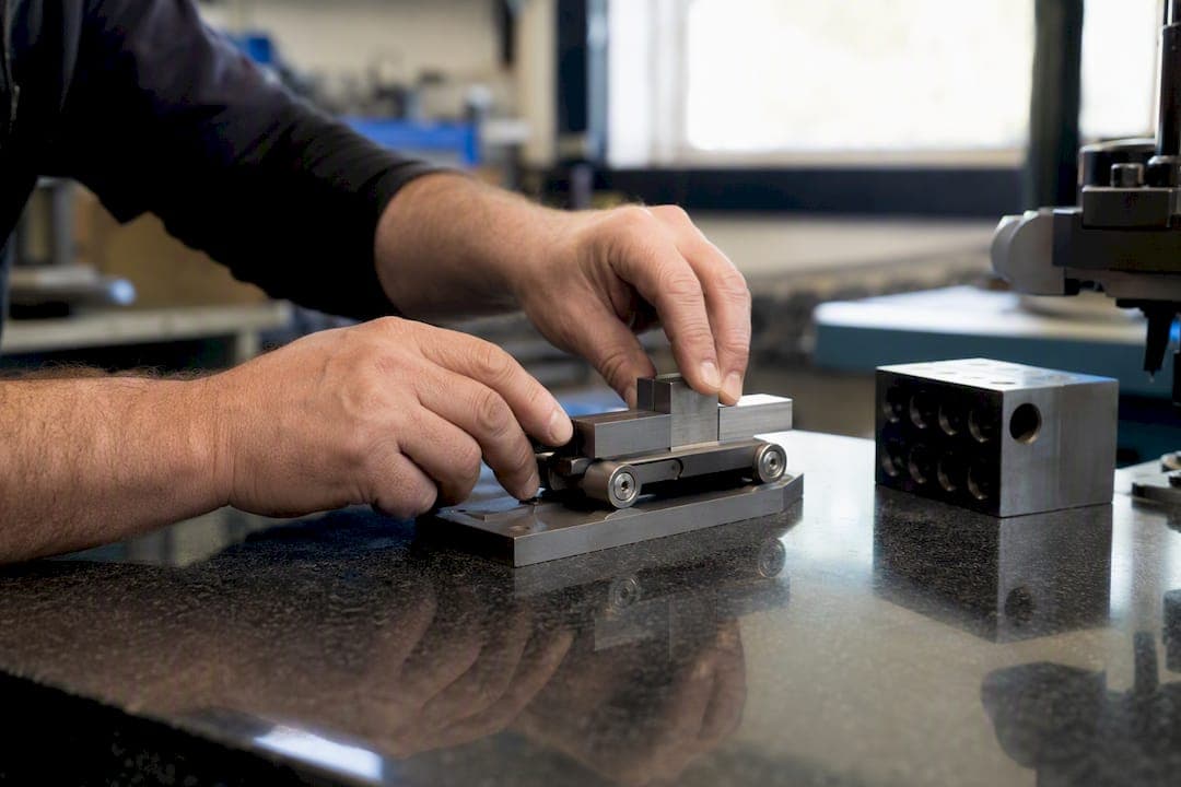
A sine bar setup comes down to one equation: H = L × sin(θ), where L is the bar's roller center distance and H is the gauge-block stack height you build under one roller. Flip it around with θ = arcsin(H / L) when you need to verify an angle you already have. That's the whole trick. Everything else is technique.
The one-line workflow: clean the surface plate and rollers, calculate H, wring your gauge-block stack, seat the sine bar with one roller riding the stack, sweep the reference surface with a dial test indicator (DTI), then clamp the workpiece and recheck.
- Standard bar lengths typically include 5" and 10" (some longer bars exist for lab work)
- Keep working angles under 60° whenever you can
Pro Tip: A 10" bar roughly doubles your angular stability compared to a 5" bar for the same gauge-block accuracy, so reach for it whenever the job tolerance is tight.
Key Takeaways
Accurate sine bar setups depend on the formula H = L × sin(θ), a minimal gauge-block stack, thermal stabilization, and a steady DTI sweep before any cut is made.
| Point | Details |
|---|---|
| Core formula | Use H = L × sin(θ) to set an angle and θ = arcsin(H / L) to verify one. |
| Bar length choice | A 10" bar roughly doubles angular stability over a 5" bar for the same block accuracy. |
| Minimize gauge blocks | Keep stacks to three or four blocks to reduce wringing-interface error. |
| Respect thermal drift | Let handled blocks sit 15 to 20 minutes before final measurement. |
| Watch the 60° cutoff | Above roughly 60°, angular sensitivity worsens fast, so prefer a sine plate or complement angle. |
Table of Contents
- What Tools Do You Need for a Sine Bar Setup?
- How Do You Set Up a Sine Bar Step by Step?
- Sine Bar Formula and Quick-Reference Table
- Why Does Sine Bar Accuracy Drop at Steep Angles?
- How Do You Verify a Sine Bar Is Set Correctly?
- What Standards and Tools Simplify Sine Bar Setup?
- Our Take on Getting Sine Bar Setups Right
- Sources
What Tools Do You Need for a Sine Bar Setup?
Start with a clean surface plate. Wipe it with a lint-free cloth and a compatible solvent, and check it against its flatness grade before trusting it for anything under a few thousandths.
Your sine bar itself should have two rollers of matched diameter, free of nicks or dried coolant. Center-to-center distance is almost always 5" or 10", and that number is your L in every calculation. Gauge blocks are where most setups go sideways. Grade 1 or Grade 2 blocks are fine for shop work (save Grade AA for the calibration lab), and the real skill is building your target height from as few blocks as possible. Wring them by sliding one face across another at a slight angle under light pressure, never by slamming them together.
For measuring, a DTI or electronic indicator confirms the setup is level and steady; a micrometer or caliper lets you verify the actual stack height before you trust it.
- Surface plate: clean, checked flatness grade
- Sine bar: matched rollers, correct L
- Gauge blocks: Grade 1/2, minimal count, proper wringing
- DTI, mic or calipers, optional planer gauge
- Let blocks sit 15 to 20 minutes before use so hand warmth doesn't skew the stack, a point the Sine Bar unit from Manufacturing Processes 4-5 covers in more detail.
How Do You Set Up a Sine Bar Step by Step?
-
Inspect and clean. Wipe down the surface plate and sine bar rollers. Check both rollers for equal diameter and confirm there's no grit or coolant residue riding along.
-
Confirm L and pick your units. Measure or check the stamped center-to-center distance, and decide now whether you're working in inches or millimeters. Mixing them mid-calculation is a classic way to be off by a factor of 25.4.
-
Calculate H. Plug your angle into H = L × sin(θ). Round only at the final step, not during intermediate math.
-
Build the gauge-block stack. Assemble from largest block to smallest, wringing each new block onto the stack with a slight rotating slide rather than a straight push. Fewer interfaces mean less accumulated error, so stop at three or four blocks if the combination allows it.
-
Seat the sine bar. Place one roller flat on the plate and the other on top of the block stack. If your bar has a clamp, lock it once you're satisfied with the position, not before.
-
Sweep with the DTI. Run the indicator across the reference face of the sine bar or the workpiece riding on it. A needle that holds steady across the full sweep means the angle is set; drift means the stack needs adjustment or the surface underneath has debris.
-
Iterate, then clamp. Nudge the stack or reseat the bar until the sweep is flat, then clamp the workpiece and sweep again. Clamping pressure can shift things by a surprising amount on thin or irregular parts.
-
Record everything. Write down the block combination, the target angle, and the verification reading. That log is what saves you twenty minutes next time you run the same job.
Pro Tip: Do the final DTI sweep after clamping, not before. Plenty of setups check out perfectly right up until the clamp torque tips the part half a thousandth off angle.
Sine Bar Formula and Quick-Reference Table
The math never changes: H = L × sin(θ) to set an angle, θ = arcsin(H / L) to check one. Keep your units consistent throughout, and if your protractor gives you degrees-minutes-seconds, convert to decimal degrees before you touch a calculator; a stray minute of arc translates into real height error on a long bar.
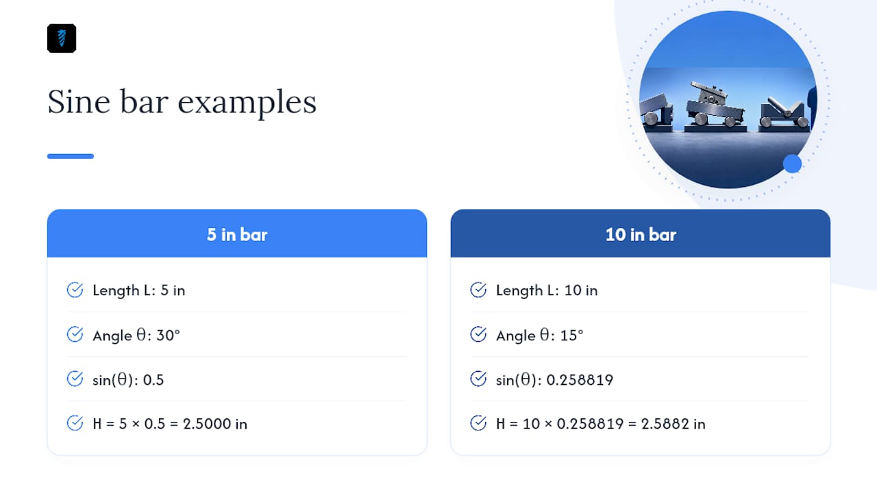
Worked examples: a 5" bar at 30° needs H = 5 × sin(30°) = 5 × 0.5 = 2.5000". A 10" bar at 15° needs H = 10 × sin(15°) = 10 × 0.258819 = 2.5882", per the arithmetic in CNC Cookbook's sine bar guide.
Use the 5" bar for tight benches and lighter parts. Reach for the 10" bar on inspection-grade work or anything past 30°, since it holds tighter angular tolerance for the same block accuracy. For taper angle calculations or compound angles, you'll often stack a sine bar with a sine plate or angle plate rather than trying to force one setup to do both jobs at once.
Why Does Sine Bar Accuracy Drop at Steep Angles?
Angular error scales with δθ ≈ δH / (L × cos θ), and cos(θ) shrinks fast as you approach 90°, so the same tiny height mistake produces a much bigger angle error near 60° or 70° than it does near 15°. A 10" bar cuts that angular error roughly in half compared to a 5" bar for identical δH, a relationship laid out by TWC's sine bar calculator.
The usual culprits: too many wringing interfaces in the block stack, thermal drift from handling, worn or dirty rollers, the wrong block combination for the target height, and clamping distortion after you thought the setup was locked in.
- Minimize block count, ideally three to four
- Wring correctly and let stacks stabilize for 15 to 20 minutes before final checks
- Verify roller diameters match before every critical job
- Favor the longer bar when the tolerance is tight
Pro Tip: At higher angles beyond about 60°, the sine bar becomes less stable and less accurate; consider using a sine plate or measuring the complementary angle to improve stability.
How Do You Verify a Sine Bar Is Set Correctly?
-
Sweep with the DTI. Run the indicator the full length of the reference surface. A steady needle across the sweep confirms the angle; note any runout for your records.
-
Back-calculate. Measure the actual stack height with a micrometer and run θ = arcsin(H / L) to confirm it matches your target, catching arithmetic mistakes before they reach the part.
-
Recheck at key moments. Sweep again after clamping, after the blocks have thermally settled, and immediately before any cut that can't be undone.
-
Calibrate for critical work. For tolerance-critical jobs, verify the sine bar itself against certified angle blocks or an autocollimator, following the multi-angle procedure Gaugify outlines for calibrating sine bars.
What Standards and Tools Simplify Sine Bar Setup?
Sine bar construction, roller hardness, and permissible tolerances trace back to Commercial Standard CS 141-47, still the reference point for what separates a shop-grade bar from a laboratory one.
On the calculation side, Availzyemachinistpro's sine bar calculator handles the arithmetic and the block selection at once:
- Computes H or θ instantly for any L, no manual trig
- Suggests minimal gauge-block combinations to cut wringing interfaces
- Converts DMS to decimal degrees automatically
- Backs a taper calculator and a counterbore calculator for related shop math
Our Take on Getting Sine Bar Setups Right
Most sine bar tutorials spend too much time on trigonometry and not enough on what actually breaks a setup: too many gauge blocks stacked together, warm hands touching cold steel right before a critical measurement, and rollers nobody bothered to check for wear. The math is the easy part. A shop apprentice can learn H = L × sin(θ) in five minutes. What takes longer to learn is discipline: stopping at three or four blocks instead of six, waiting the fifteen minutes for thermal drift to settle, and sweeping the indicator again after you clamp instead of trusting the number you calculated an hour ago.
If we had to pick one habit to fix first, it's the block count. Every extra wringing interface is a small, real source of error that compounds with the next one, and it's the single easiest variable to control on any bench. Bar length matters too, but you can't always swap a 5" bar for a 10" one mid-job. You can almost always trim your block stack down by one.
— Availzye
Sources
- Sine Bars, Blocks, Plates, and Fixtures (Commercial Standard CS 141-47)
- Sine bar, Sine plate, Sine vise — complete guide
- CNC Sine Bar Calculator – Block Height & Angle Setup - TWC Industrial Calculators