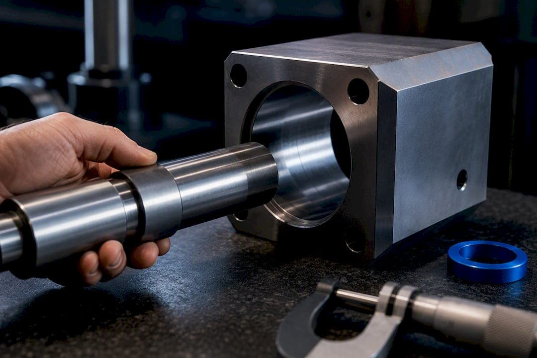
Use ISO 286 whenever you need International Tolerance grades and fundamental deviations for a hole or shaft, and use ISO 2768 for dimensions your drawing leaves unspecified. Both standards work together, not in competition. For actual size calculations, a verified limits-and-fits calculator will compute maximum and minimum sizes and the resulting clearance or interference faster and with fewer transcription errors than a manual table lookup.
TL;DR:
- ISO 286 tolerance grades range from IT01 to IT18, with lower numbers indicating tighter, more expensive tolerances suitable for precision components.
- Fundamental deviation letters (H, g, k, p) specify the position of the tolerance zone relative to the basic size, affecting whether a fit is clearance, transition, or interference.
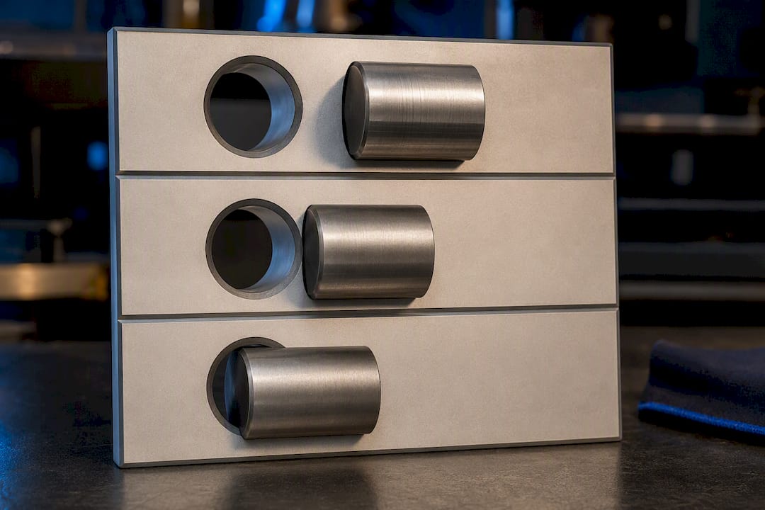
- An ISO fit like 25 H7/g6 typically results in a clearance fit, suitable for rotating or sliding parts, but changing the shaft deviation to k6 creates a transition fit, and p6 yields interference fit.
- Automated calculators and embedded shop floor tools improve accuracy and workflow by directly computing limit sizes, clearance, interference, and fit classification from the callout.
- A proper selection balances manufacturing capability, inspection resolution, and functional needs to prevent costly over-specification or assembly issues.
Table of Contents
- Tolerance Tables ISO 286: How IT Grades Set Your Precision Band
- Fundamental Deviations: Decoding the Letters in H7, g6, and Similar Codes
- How to Calculate an ISO Fit: 25 H7/g6 Worked Step by Step
- Choosing a Limits-and-Fits Calculator: What to Look For and How to Verify Results
- ISO 2768 General Tolerances: When You Don't Need a Specific Callout
- A Checklist for Picking the Right IT Grade and Fit
- Software-Assisted Tolerance Lookups on the Shop Floor
- Where ISO Tolerance Tables Came From and Why the System Works This Way
- ISO 286 Versus ANSI/ASME and JIS Tolerance Systems
- Industries That Depend on ISO Tolerance Tables Daily
- Where ISO Tolerance Tables Break Down in Real Shops
- Primary Standards and Trusted Calculators to Bookmark
- Balancing Tolerance Selection, Inspection, and Throughput
- Try Availzye Machinist Pro for Tolerance Lookups That Stay With the Job
- Sources
- FAQ
Tolerance Tables ISO 286: How IT Grades Set Your Precision Band
Every dimension you machine carries an invisible cost curve, and the IT grade number is what controls it. The International Tolerance system, defined in ISO 286, runs from IT01 through IT18. Lower numbers mean tighter tolerance zones and higher cost to produce; higher numbers mean looser zones and cheaper production. That is the entire logic of the system in one sentence, and almost everything else in this article builds on it.
An IT grade by itself does not tell you a size. It tells you a width, in micrometers, that gets applied around a basic size once you also know the fundamental deviation (the letter code covered in the next section). Think of the IT grade as the size of the box, and the deviation letter as where that box sits relative to the nominal dimension.
The Engineers Edge IT grades chart, built from ISO 286-1, shows how those tolerance widths change across nominal size bands. A tighter grade like IT6 might allow a variation in the low tens of micrometers on a 25mm shaft, while IT11 on the same nominal size allows a much larger tolerance, roughly an order of magnitude greater.
Representative IT grade values by size band
These are excerpted from the standard's broader table, which extends well past 500mm and down to grades finer than IT01. Notice the pattern: for a given IT grade, the tolerance width grows as the nominal size grows, because holding an absolute micrometer value gets proportionally harder on a larger part.
A few practical notes worth keeping in your back pocket when you're picking a grade:
- IT01 through IT4 are reserved for gauge blocks, precision bearings, and other applications where standard shop equipment often cannot hold the tolerance without specialized grinding or lapping.
- IT5 through IT10 cover most conventional machining, from ground shafts to turned and milled components.
- IT11 through IT18 apply to non-precision work like sheet metal, castings, and clearance holes for fasteners.
- The finest grades (IT01, IT0, IT1) carry special applicability notes in the standard itself and are not commonly specified outside metrology labs.
That last point matters more than it looks. Specifying IT5 on a bracket that only needs to bolt to a frame is not precision, it's waste. Specifying IT11 on a bearing bore is not economy, it's a warranty claim waiting to happen. Matching the grade to the function is the actual skill here, and it's one the tolerance stack up discipline depends on when you're chaining multiple toleranced features through an assembly.
Fundamental Deviations: Decoding the Letters in H7, g6, and Similar Codes
The letter in a fit callout tells you where the tolerance zone sits relative to the basic size, and the case tells you whether it applies to a hole or a shaft. Uppercase letters (H, G, K, P) describe holes. Lowercase letters (h, g, k, p) describe shafts. That capitalization is not a typographic accident. It's load-bearing information.
Each letter corresponds to a specific fundamental deviation, defined as the distance between the tolerance zone and the basic size, measured to whichever limit is closest to zero. H is the most common hole designation because its lower deviation is fixed at zero. The hole's minimum size equals the nominal size exactly, and the tolerance only ever adds material upward. That single design choice is why hole-basis systems built around H dominate industrial practice: it gives you one predictable reference surface and lets the shaft's letter do all the fit adjustment.
Deviations run in a standardized alphabetical sequence from A (largest positive deviation, used for holes) down through H (zero) and on to Z (largest negative). Shaft letters mirror this in reverse. Here's how a handful of common ones break down for a 25mm nominal size:
| Deviation letter | Type | Upper deviation ES/es (µm) | Lower deviation EI/ei (µm) |
|---|---|---|---|
| H7 (hole) | Zero-based | +— | 0 |
| G6 (hole) | Small positive | +20 | +7 |
| K7 (hole) | Straddles zero | +6 | −— |
| g6 (shaft) | Small negative | −7 | −20 |
| h6 (shaft) | Zero-based | 0 | −— |
| k6 (shaft) | Small positive | +— | +2 |
A quick sign-reading rule: for holes, ES is the upper deviation and EI is the lower. For shafts, es is upper and ei is lower. Positive values push material outward from nominal (bigger holes, bigger shafts); negative values pull it inward (smaller holes, smaller shafts). When a deviation range straddles zero, like K7 or k6, the tolerance zone overlaps the nominal line, which is exactly what makes those letters useful for transition fits.
To turn any of this into an actual physical size, you add the deviation (in millimeters) to the nominal dimension:
- Maximum hole size = nominal + ES
- Minimum hole size = nominal + EI
- Maximum shaft size = nominal + es
- Minimum shaft size = nominal + ei
That arithmetic is trivial once you have the right numbers pulled from the table. The harder part, in practice, is not making an arithmetic mistake when you're doing it by hand across a dozen dimensions on a drawing. That's precisely the failure mode a calculator eliminates, which the next section covers with real numbers.
How to Calculate an ISO Fit: 25 H7/g6 Worked Step by Step
A fit callout like 25 H7/g6 packs three pieces of information into eight characters: the nominal size (25mm), the hole tolerance (H7), and the shaft tolerance (g6). Reading it correctly is a five-step process, and running the numbers takes less time than it takes to explain them.
- Identify the nominal size band. 25mm falls in the "over 18 to 30" range in the ISO 286 tables.
- Look up the hole deviation. For H7 at this size band, ES = +0.021mm and EI = 0mm.
- Look up the shaft deviation. For g6 at this size band, es = −0.007mm and ei = −0.020mm.
- Compute the four limit sizes. Hole: max = 25.021mm, min = 25.000mm. Shaft: max = 24.993mm, min = 24.980mm.
- Calculate clearance or interference. Maximum clearance = hole max − shaft min = 25.021 − 24.980 = 0.041mm. Minimum clearance = hole min − shaft max = 25.000 − 24.993 = 0.007mm.
Pro Tip: Since both clearance values come out positive, 25 H7/g6 is a clearance fit across its entire range, the kind you'd specify for a shaft that needs to rotate or slide freely in a bushing, such as a spindle running in a plain bearing.
Compare that against two other common callouts to see how the same math produces three completely different fit behaviors.
25 H7/k6 (transition fit). Using k6 deviations at this size band (es = +0.015mm, ei = +0.002mm), the shaft runs from 25.015mm to 25.002mm. Hole limits stay the same: 25.021mm to 25.000mm. Maximum clearance = 25.021 − 25.002 = 0.019mm. Maximum interference = 25.000 − 25.015 = −0.015mm (interference, since the shaft can be larger than the hole). A transition fit like this is what you'd specify for a dowel pin or a gear hub that needs precise location but occasional disassembly.
25 H7/p6 (interference fit). With p6 deviations (es = +0.035mm, ei = +0.022mm), shaft limits run from 25.035mm to 25.022mm, both above the hole's maximum of 25.021mm. Every possible combination of hole and shaft size produces interference, from 0.001mm to 0.035mm. That's a press fit, the kind used to permanently mount a bearing race or a pulley onto a shaft without a keyway.
The pattern across all three examples: the hole tolerance stayed fixed at H7, and the fit character changed entirely based on which shaft letter and grade you paired it with. That's the hole-basis system doing its job, letting one reference tolerance serve three completely different mechanical outcomes.
Choosing a Limits-and-Fits Calculator: What to Look For and How to Verify Results
Manual table lookups work fine for a single dimension. They get error-prone fast once you're checking a full drawing package or running the same fit calculation across a family of parts. That's the gap online calculators fill, and several engineering-grade tools now handle it cleanly.
A calculator built on ISO 286, like the one from MESYS, takes a nominal size and a tolerance field (H7, g6, or whatever your callout specifies) and returns the ES/EI or es/ei values automatically, then computes the resulting max and min sizes and the clearance or interference range. Xometry Pro's ISO 286 calculator works similarly, displaying hole basis and shaft basis options side by side along with the classified fit type. Trelleborg offers a comparable tool aimed at seal and bearing fit selection.
What you should expect any solid calculator to return:
- Nominal size and the tolerance class you entered (H7, g6, k6, etc.)
- Upper and lower deviations in micrometers or millimeters
- Calculated maximum and minimum sizes for both hole and shaft
- Maximum clearance and maximum interference values
- A fit classification (clearance, transition, or interference)
The speed advantage is real. Providers building these tools consistently point to reduced lookup errors as the main reason shops switch away from manual chart reading, especially for batch checks across multiple mating parts. But speed only helps if the numbers coming out are correct, and that means treating a calculator's output the way you'd treat a CMM report: trust it, but verify the source.
Before you rely on any calculator for a production drawing, confirm which edition of ISO 286 it's built on (the standard has been revised, and older tools sometimes carry legacy deviation tables). Run one dimension by hand against the Engineers Edge chart as a sanity check, then save the verified calculator output directly into your CAD model's tolerance notes so the next engineer who opens the file doesn't have to redo the lookup from scratch.
ISO 2768 General Tolerances: When You Don't Need a Specific Callout
Not every dimension on a drawing needs an explicit ISO 286 fit. That's what ISO 2768 exists for, and it's the standard that quietly saves engineers hours of over-specification on features that simply don't need tight control.
ISO 2768 splits into two parts. ISO 2768-1 covers linear and angular dimensions using four tolerance classes: f (fine), m (medium), c (coarse), and v (very coarse). ISO 2768-2 handles geometric tolerances like flatness, straightness, and perpendicularity for parts where those form errors matter but don't justify a full GD&T callout.
A single note on the drawing title block, something like "ISO 2768-mK," applies a default tolerance to every dimension that doesn't carry its own explicit tolerance. That single note replaces what could otherwise be dozens of redundant plus/minus callouts cluttering the print.
Representative ISO 2768-1 linear tolerance values
Medium (m) is the default most shops fall back on for general machined features, structural brackets, and non-mating surfaces. Fine (f) shows up on parts with some cosmetic or light functional requirement but no fit relationship. Coarse and very coarse belong on weldments, castings, and rough stock dimensions.
The line between "use ISO 2768" and "specify ISO 286 explicitly" is simple in practice: the moment a dimension mates with another part, locates a bearing, or forms half of a fit, it needs an explicit tolerance class from ISO 286. General tolerances are for everything else, the dimensions that just need to be "close enough" for form, fit-adjacent clearance, or appearance.
A Checklist for Picking the Right IT Grade and Fit
Choosing a tolerance isn't a lookup problem, it's a functional-requirements problem that happens to end with a lookup. Run through these questions before you commit a callout to a drawing.
- Does the part rotate or slide relative to its mate? If yes, you need a clearance fit, likely H7/g6 or H7/f7 depending on speed and lubrication.
- Does the joint carry a static load without relative motion? Interference fits like H7/p6 or H7/s6 are appropriate, but check that your press equipment can actually achieve the required force without damaging either part.
- Does the assembly need occasional disassembly for maintenance? A transition fit (H7/k6 or H7/n6) balances location accuracy against serviceability, common on gear hubs and locating dowels.
- What IT grade can your process actually hold? Turning and milling on a well-maintained machine typically holds IT8 to IT10 reliably. Grinding gets you into IT5 to IT7 territory. Don't specify a grade your shop floor can't produce without secondary operations.
- Can your inspection equipment measure the tolerance you're specifying? A caliper reading to 0.02mm has no business verifying an IT6 dimension that requires micrometer or CMM-level resolution.
Pro Tip: Match the fit to the failure mode you're most afraid of. If a loose fit causes vibration and wear, err tighter. If a tight fit causes assembly damage or seized parts, err looser. The "safe" direction isn't universal, it depends entirely on what breaks first.
A few red flags worth catching before a drawing goes to the floor: tolerance stack-up across a chain of mating dimensions that quietly eats your clearance budget (worth running through a proper stack-up analysis before release), inspection capability that can't actually confirm the tolerance you specified, and press-fit assembly methods applied to parts with sharp internal corners or thin walls that will crack under interference load. Reference the press fit guide for a closer look at interference fit failure modes before you lock in a p6 or s6 shaft.
Software-Assisted Tolerance Lookups on the Shop Floor
Manual charts and standalone calculators both work, but neither one lives where the rest of your job data does. Availzye Machinist Pro's tolerance calculator handles the ISO 286 lookup and limit calculations directly, alongside dedicated calculators for bolt circles and thread drills that come up on the same prints.
The bigger difference shows up in workflow, not just calculation. A fit result computed in isolation gets forgotten the moment you close the browser tab. One tied to a work order in the Job Tracker stays attached to the part it belongs to, visible to whoever picks up that job next. Pair that with the built-in CAD viewer for checking mating geometry and document storage for keeping the verified tolerance callout with the drawing revision, and the calculation stops being a one-off lookup and becomes part of the job record.
For a shop running the same fit calculations across dozens of similar parts every week, that persistence matters more than raw calculation speed. The math is identical to what a free calculator gives you. Where it belongs afterward is the actual problem worth solving.
Where ISO Tolerance Tables Came From and Why the System Works This Way
The limits-and-fits concept predates ISO by decades. Interchangeable manufacturing, the idea that a part made in one factory should fit a mating part made in another, forced engineers in the late nineteenth and early twentieth centuries to standardize how much size variation was acceptable. National systems developed independently: Britain, Germany, and the United States each built their own tolerance grading schemes before international trade made those differences a genuine problem.
ISO consolidated these national systems into a single international framework, formalized as ISO 286, built around two core ideas: a graduated series of tolerance widths (the IT grades) that scale sensibly with part size, and a standardized set of deviation letters that let a hole and a shaft be specified independently yet still combine predictably into a known fit.
The hole-basis preference, where H becomes the default hole tolerance, exists for a practical shop reason rather than a mathematical one. Reamers, broaches, and other hole-finishing tools are typically built to a fixed size, so it's cheaper to standardize the hole and vary the shaft with adjustable turning or grinding operations than the reverse. That manufacturing reality, more than any abstract preference, is why H-basis fits dominate industrial drawings even today.
ISO 286 Versus ANSI/ASME and JIS Tolerance Systems
Engineers working across international supply chains run into three major tolerance systems: ISO 286, the American ANSI/ASME Y14.5 and B4.1 standards, and the Japanese JIS B 0401 system. The good news is that JIS B 0401 is functionally aligned with ISO 286, using the same IT grade numbering and deviation letter logic, since Japan adopted the ISO framework directly into its national standard.
ANSI/ASME diverges more. American limits and fits historically used a separate classification (RC for running/sliding clearance, LC for locational clearance, FN for force/interference fits) built around inch dimensions rather than the metric IT grade system. The underlying engineering logic, clearance versus transition versus interference, is the same, but the letter codes and reference tables don't translate directly. A print calling out "RC4" carries no direct ISO 286 equivalent without converting through the actual dimensional limits.
For any shop or design team working exclusively in one system, this rarely causes trouble. It becomes a real risk on drawings inherited from an overseas customer or supplier, where an ANSI callout gets mistakenly read against an ISO fits chart, or vice versa. When a print crosses that boundary, convert to actual dimensional limits and compare numbers directly rather than trying to match letter codes across systems.
Industries That Depend on ISO Tolerance Tables Daily
Precision manufacturing runs on ISO 286 wherever parts from different suppliers, or different production runs, need to assemble without hand-fitting. Automotive powertrain components, bearing bores and shafts, hydraulic and pneumatic cylinder assemblies, and gearbox housings all rely on consistent fit classes to keep interchangeability intact across high-volume production.
Aerospace manufacturing pushes toward the tighter end of the IT grade range, often IT5 through IT7, on structural fasteners and rotating assemblies where weight and fatigue margins leave no room for a loose fit. Medical device manufacturing follows a similar pattern on implantable and surgical instrument components, where tolerance directly affects biocompatible fit and mechanical reliability.
Mold and die work leans on ISO fits for guide pins and bushings, where a transition or light interference fit keeps the tooling aligned over millions of cycles without excessive wear. Specialized precision fields extend the same discipline further. Tight-tolerance glass machining, for instance, applies comparable fit logic to a material with almost none of steel's forgiving ductility, where a few micrometers of deviation changes whether a component seats correctly at all.
Even general fabrication and sheet metal work benefit indirectly. Knowing when a dimension does not need an ISO 286 callout, and can default to ISO 2768 instead, keeps drawings for brackets, enclosures, and weldments from being over-specified and needlessly expensive to inspect.
Where ISO Tolerance Tables Break Down in Real Shops
The standard is not the problem. Misapplying it is. The most common failure isn't picking the wrong letter, it's picking a tolerance the shop's actual equipment can't hold consistently. A design engineer specifies H7/g6 because it's the "standard" clearance fit taught in every textbook, without checking whether the shop's lathes are holding IT7 on a good day or an exceptional one.
Tolerance stack-up is the second recurring trap. Individual dimensions can each sit comfortably within their IT grade, and the assembly can still fail because three or four toleranced features compound in the same direction. A worst-case stack calculation, not just individual fit checks, catches this before it becomes a rework problem on the floor.
Inspection capability gets overlooked just as often. Specifying IT6 on a dimension that only gets checked with a dial caliper accurate to 0.02mm means the inspection method can't actually confirm conformance, so you're trusting the machine's repeatability rather than verifying it. Pairing a chosen IT grade with process capability data, Cp and Cpk figures from your own equipment, closes that gap before parts ship.
Finally, treating fit selection as a lookup exercise rather than a functional decision causes real cost. Reflexively defaulting to H7/g6 on every rotating shaft ignores load, speed, and lubrication conditions that might actually call for a looser f7 fit or a tighter h6, and the difference shows up in tool wear and bearing life long after the drawing is signed off.
Primary Standards and Trusted Calculators to Bookmark
For the official standard text and table previews, the ISO Online Browsing Platform is the primary source, though full access to the definitive tables requires purchasing the standard. Free previews are useful for confirming clause structure and terminology, but production drawings should reference a purchased or licensed copy for legal traceability.
For calculation, MESYS and Xometry Pro both compute ES/EI, es/ei, max/min sizes, and fit classification directly from a nominal size and tolerance field. Trelleborg's calculator offers a similar function with a seal-and-bearing focus. For quick IT grade reference tables without running a calculation, the Engineers Edge chart lays out ISO 286-1 values across the full nominal size range.
Balancing Tolerance Selection, Inspection, and Throughput
The real tension on any shop floor isn't ISO 286 versus ISO 2768, it's precision versus throughput. A tighter IT grade slows cycle time, increases scrap risk, and demands better gauging. Pairing calculator output with actual process capability data before committing to a fit avoids the worst outcome: a print that's technically correct and practically unmanufacturable at volume.
Run a pilot batch before finalizing a tight fit on a new part number, and write the chosen tolerance class and inspection method directly into the drawing notes. That documentation habit costs a few minutes and saves the argument that inevitably happens three months later when nobody remembers why a dimension was toleranced the way it was.
— Availzye
Try Availzye Machinist Pro for Tolerance Lookups That Stay With the Job
A free calculator gets you a fit result. It doesn't keep that result attached to the part, the revision, or the technician running it next shift. Availzye Machinist Pro closes that gap: the tolerance calculator handles ISO 286 limits and fits alongside bolt circle and thread drill math, and results live inside the same platform as your Job Tracker work orders and CAD viewer.

That means a fit calculation for a bushing bore doesn't just sit in a browser tab, it stays attached to the job record where the next machinist or inspector can find it. Subscription plans with different tiers are available for individual users, small shops, and teams, with each tier including a free trial period. Run your next fit calculation on a real part number and see whether it fits into your shop's workflow before you commit to anything.
Sources
- Welcome to the Online Browsing Platform (OBP)
- International Tolerance (IT) Grades ISO 286-1 - 2010(E) Table Chart
- Calculation of fits (MESYS AG)
- ISO 286 Limits and Fits Calculator — Xometry Pro
FAQ
What is the ISO standard for tolerances?
ISO 286 governs limits and fits for holes and shafts, defining IT grades and fundamental deviations. ISO 2768 separately covers general tolerances for dimensions a drawing leaves unspecified.
What is the ISO 286 tolerance table?
It's the reference table mapping IT grades (IT01 through IT18) to tolerance widths in micrometers across nominal size bands, combined with fundamental deviation letters like H, g, and k that position the tolerance zone relative to nominal size. The full ISO 286 text is previewable on the ISO Online Browsing Platform.
What is h6 and H7 tolerance?
H7 is a common hole tolerance with zero lower deviation and a small positive upper deviation, meaning the hole never comes in smaller than nominal. h6 is the shaft equivalent, with zero upper deviation, meaning the shaft never runs larger than nominal. Paired as H7/h6, they form a very light clearance or near-line-to-line fit often used for locating fits with easy assembly.
What's the difference between clearance, transition, and interference fits?
A clearance fit always leaves a gap between hole and shaft, suited to rotating or sliding parts. A transition fit can produce either a small clearance or a small interference depending on where actual sizes land within tolerance, common for locating dowels. An interference fit always requires the shaft to be larger than the hole, used for permanent press-fit assemblies like bearing races.