
GD&T symbols are the graphical shorthand engineers use to control how a part's form, orientation, location, profile, and runout deviate from ideal geometry, rather than just its size. This reference covers every core symbol defined by ASME Y14.5, how to read a Feature Control Frame, and what each symbol actually demands on the shop floor. Availzye Machinist Pro built it as the single page you pull up when a drawing callout needs a fast, correct answer.
TL;DR:
- Most GD&T symbols create specific tolerance zones, with form controls like straightness, flatness, circularity, and cylindricity requiring no datum references.
- Position, concentricity, and symmetry depend on datums, but concentricity is rarely used due to measurement challenges on CMMs.
- Inspection methods vary from surface plates for flatness to CMMs and functional gages, with production favoring gages for speed in high-volume parts.
- Using the correct symbol and modifiers like MMC ensures proper control of virtual conditions and bonus tolerances without unnecessary complexity.
- Sharing a common understanding of GD&T symbols and keeping cheat charts accessible reduces rework and inspection disputes on the shop floor.
Table of Contents
- What Do GD&T Symbols Mean? A Full Reference Chart
- How the Five GD&T Categories Shape Your Tolerance Zone
- Reading a Feature Control Frame and Its Modifiers
- Datums and the Datum Reference Frame Explained
- Which Inspection Method Fits Which Symbol
- Where GD&T Misuse Actually Costs You Time
- Printable GD&T Charts Worth Keeping on Hand
- Why Shared Symbol Knowledge Changes Shop Outcomes
- Your Next Tolerance Question Doesn't Need a Standard Lookup
- Sources
- FAQ
What Do GD&T Symbols Mean? A Full Reference Chart
Fourteen core geometric characteristic symbols make up the GD&T vocabulary in ASME Y14.5-2018, and each one belongs to one of five categories: form, profile, orientation, location, or runout. Learning them isn't about memorizing glyphs. It's about knowing what shape of tolerance zone each symbol creates and what that zone actually restricts on a real feature.
Form controls (straightness, flatness, circularity, cylindricity) never require a datum because they only judge a feature against itself. Everything else, from profile through runout, needs at least one datum reference to define what the feature is being measured relative to.
Form Symbols
- Straightness — controls how far a line element deviates from a perfectly straight line. No datum required. Typically checked with a dial indicator sweep or a CMM line scan.
- Flatness — controls deviation of a surface from a perfect plane, creating a tolerance zone of two parallel planes. No datum required. Checked on a surface plate with an indicator or optically with a CMM.
- Circularity (Roundness) — controls how much a cross-section deviates from a true circle at any single station. No datum required. Best measured with a dedicated roundness tester rather than a caliper.
- Cylindricity — controls circularity, straightness, and taper simultaneously along the full length of a cylindrical feature. No datum required. Usually a CMM or roundness tester with axial scanning.
Profile Symbols
- Profile of a Line — controls a two-dimensional cross-section against a boundary of offset curves. Datum sometimes required depending on the callout. Checked with optical comparators or CMM cross-sections.
- Profile of a Surface — controls an entire 3D surface within a tolerance zone that follows the true profile, offset equally on both sides. Datum usually required. Typically inspected with a CMM or laser scanner against nominal CAD data.
Orientation Symbols
- Parallelism — controls a surface or axis so it stays equidistant from a datum plane or axis. Datum required. Checked with a height gage or CMM referenced to the datum.
- Perpendicularity — controls a 90 degree relationship between a feature and a datum. Datum required. Checked with a square and indicator or a CMM.
- Angularity — controls a feature at a specified basic angle other than 90 degrees relative to a datum. Datum required. Sine plates or CMM angular measurement are common.
Location Symbols
- Position — the most heavily used symbol in the entire standard. It creates a cylindrical (or, for a plane feature, a two-plane) tolerance zone locating a feature relative to datums, and it supports MMC and LMC modifiers for bonus tolerance. Datum required. Inspected with a CMM or a functional gage at MMC.
- Concentricity — controls the coincidence of median points of a feature relative to a datum axis. Datum required. Rarely specified anymore because it demands derived median-point measurement that most CMM software struggles to execute reliably.
- Symmetry — controls the coincidence of median points of two features relative to a datum plane. Datum required. Same practical inspection problem as concentricity, and ASME guidance steers designers toward position or profile instead whenever possible.
Runout Symbols
- Circular Runout — controls variation at a single cross-section as a part rotates around a datum axis, catching circularity and coaxiality errors together. Datum required. Checked with an indicator and V-block or a rotary table setup.
- Total Runout — controls variation across the entire surface as the part rotates, combining circularity, straightness, coaxiality, and taper. Datum required. Checked with an indicator swept along the full length while the part rotates on a datum axis.
| Category | Symbols | Datum needed? | Zone shape |
|---|---|---|---|
| Form | Straightness, flatness, circularity, cylindricity | No | Line, two planes, circle, cylinder |
| Profile | Line, surface | Sometimes | Offset boundary curve or surface |
| Orientation | Parallelism, perpendicularity, angularity | Yes | Two parallel planes or lines |
| Location | Position, concentricity, symmetry | Yes | Cylinder or two planes |
| Runout | Circular, total | Yes | Annular zone per section or full surface |
A laminated version of this chart at the CNC station saves more time than most people expect. If a printable version sounds useful, the GD&T Symbols Chart covers the same 14 symbols with inspection notes built in, and it holds up well taped inside a toolbox lid.
How the Five GD&T Categories Shape Your Tolerance Zone
Every GD&T symbol belongs to a category, and the category tells you the shape of the tolerance zone before you even read the numeric value.
- Form zones bound a single feature against itself: two parallel planes for flatness, a line for straightness, a circle for circularity, a cylinder for cylindricity. No datum enters the picture because form is a self-referential check, which is exactly why it's the cheapest category to inspect and the first thing to verify before checking anything else.
- Profile zones follow an offset boundary traced around the true profile, either as a 2D line or a full 3D surface. This is the category to reach for when a feature has a complex or curved geometry, like a cam lobe or a sculpted surface, that flatness or straightness can't describe.
- Orientation zones (parallelism, perpendicularity, angularity) are always two parallel planes or lines set at a fixed angular relationship to a datum. A milled slot that has to stay parallel to a mounting face is the textbook use case.
- Location zones pin a feature's position relative to a datum reference frame, typically as a cylinder around the true position for a hole or boss. Bolt patterns and dowel holes live here almost exclusively, which is why position is the workhorse symbol of the whole standard.
- Runout zones are built around rotation. Circular runout checks single cross-sections; total runout checks the whole surface as the part spins on its datum axis. Anything that spins in a bearing or chuck (shafts, pulleys, spindle noses) belongs in this category.
ASME groups these five categories the same way internationally recognized standards do, though ISO drawings sometimes phrase profile and orientation callouts with slightly different symbol combinations. That's a detail worth flagging to a supplier reading a foreign print, but it rarely changes the underlying geometry being controlled.
Reading a Feature Control Frame and Its Modifiers
The Feature Control Frame is the boxed callout on a drawing that actually carries the tolerance instruction, and it reads left to right in a fixed order: geometric symbol, tolerance value (with a diameter symbol if the zone is cylindrical), then up to three datum letters in priority order, primary first.
Modifiers sit inside that tolerance compartment and change what the number means:
- MMC (Maximum Material Condition) applies the tolerance at the feature's tightest limit (smallest hole, largest pin) and grants bonus tolerance as the feature departs from that condition, which is why a hole machined slightly oversize can still pass at a looser position tolerance than the frame states.
- LMC (Least Material Condition) does the reverse, tying the stated tolerance to the loosest material limit and is mostly reserved for wall-thickness or minimum-clearance concerns.
- RFS (Regardless of Feature Size) is the default when no modifier appears. The stated tolerance applies no matter what size the feature actually measures, with no bonus tolerance available.
- Projected tolerance zone shifts the tolerance zone off the part surface and out into space, commonly used for threaded holes where a mating bolt's actual engagement length matters more than the hole itself.
Rule #1, the envelope principle, quietly governs all of this: a feature of size must have perfect form at MMC, so a hole machined at its smallest allowed diameter can't also be bowed or tapered beyond that boundary.
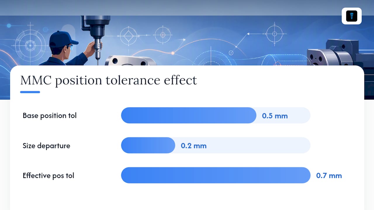
Picture a bolt hole toleranced at position 0.5 mm diameter with an MMC modifier at a 10 mm nominal diameter. Machine that hole slightly larger, say 10.2 mm, and the position tolerance effectively grows to 0.7 mm, the bonus equal to the size departure. That combined worst-case boundary is the virtual condition, and it's the number a functional gage pin is actually built to.
Pro Tip: When a print calls out MMC on a hole pattern, a functional gage that mimics the virtual condition clears parts faster than a CMM program and settles disputes on the floor immediately, since a pin that drops in either passes or it doesn't.
Datums and the Datum Reference Frame Explained
A datum is a theoretically exact reference point, axis, or plane that other features get measured against, and a Datum Reference Frame stacks three of them (primary, secondary, tertiary) into three mutually perpendicular planes that lock a part's position in space for measurement.
Datum selection should follow function, not convenience. The primary datum should be the surface that actually contacts the mating part in the assembly, not just the flattest or easiest surface to fixture. That's the single most common gap between what a print says and what an inspector's fixture actually does.
- Pick the primary datum from the surface with real functional contact in the final assembly.
- Choose secondary and tertiary datums for stability and repeatable orientation, generally the next largest and most rigid surfaces.
- Use datum targets (points, lines, or small areas) rather than an entire surface when a feature is cast, forged, or otherwise too rough or interrupted for a full-surface datum, per the approach GeoTol outlines for interrupted or rough datum surfaces.
- Establish datums in the order the frame lists them; changing that order on a fixture changes what "in tolerance" even means for the part.
Fixture design should mirror the DRF exactly. A CMM program that clamps a part in a different sequence than its datum priority will report failures that don't actually exist on the shop floor.
Which Inspection Method Fits Which Symbol
Matching the inspection method to the symbol keeps both cost and cycle time under control. Surface-plate checks are fast and cheap; CMM programs are flexible but slower per part; functional gages are the fastest for high-volume production once they're built.
| Symbol | Common inspection method | Typical use case |
|---|---|---|
| Flatness | Surface plate + indicator, or CMM | Mounting faces, seal surfaces |
| Circularity | Roundness tester or CMM | Bearing journals, pins |
| Cylindricity | Roundness tester with axial scan, or CMM | Precision shafts, bores |
| Position (MMC) | Functional gage or CMM | Bolt patterns, dowel holes |
| Circular/total runout | Indicator + V-block, rotary table | Spinning shafts, pulleys |
CMMs handle nearly every symbol on a drawing, which makes them the default choice for prototype and low-volume work, but a functional gage still wins on a production line running thousands of the same part, because a go/no-go check takes seconds instead of a multi-minute CMM cycle.
A single feature control frame can require two entirely different tools, since a position callout with an MMC modifier might get checked with a functional gage on the line and a full CMM report during first-article inspection.

Where GD&T Misuse Actually Costs You Time
GD&T exists to communicate design intent clearly. When a print piles on symbols the part doesn't functionally need, it does the opposite: it slows inspection and invites arguments between engineering and the floor.
The most persistent mistakes: calling out concentricity or symmetry when position would do the same job with far easier inspection, referencing datums inconsistently between features, and letting basic dimensions drift between revisions without updating the frame.
- Default to position over concentricity or symmetry whenever the design intent allows it.
- Use datum targets on rough or cast surfaces instead of forcing a full-surface datum.
- Document the restrained or free-state measurement condition for parts that flex, since GD&T misuse compounds fastest on thin or compliant features.
Pro Tip: A print that calls out ten separate GD&T controls on one small bracket almost always has a design intent problem hiding underneath, not a tolerancing problem.
Printable GD&T Charts Worth Keeping on Hand
The official word on every symbol lives in ASME Y14.5, and a single-page chart earns its spot on a shop wall precisely because it puts the standard's answers within arm's reach instead of a locked file cabinet.
- Keep a printable GD&T chart at every CMM station and inspection bench.
- Use posters in new-hire training so operators and inspectors apply symbols the same way from day one.
- When drawings cross language boundaries with suppliers, pair the chart with clear technical documentation practices so a symbol's meaning survives translation intact.
Why Shared Symbol Knowledge Changes Shop Outcomes
Rework and inspection disputes drop fast once a shop agrees on what every symbol actually requires. Availzye Machinist Pro builds tolerance and inspection reference tools around exactly that gap, because the cost of a misread feature control frame almost never shows up until the part fails final inspection.
— Availzye
Your Next Tolerance Question Doesn't Need a Standard Lookup
Between reading a feature control frame correctly and knowing whether a hole clears its virtual condition, the actual bottleneck is usually speed, not knowledge. Availzye Machinist Pro puts a tolerance calculator next to your feeds-and-speeds math and your job tracker, so an MMC bonus-tolerance question gets answered in the same window where you're already running the job, instead of a separate spreadsheet or a dog-eared copy of Y14.5.

The platform offers several subscription plans including Individual, Small Shop, and Team options, all available through a 7-day free trial on the Availzye Machinist Pro landing page. It doesn't replace the standard. It replaces the time you spend hunting through it mid-shift. Start the trial and run your next tolerance stack through it before you commit a part to the machine.
Sources
- ASME Y14.5 dimensioning & tolerancing
- GD&T Symbols Reference Guide | GD&T Basics
- GD&T Symbols Chart: All 14 Symbols per ASME Y14.5 (MakerStage)
FAQ
What Are the 14 Symbols in GD&T?
The 14 core symbols cover five categories: form (straightness, flatness, circularity, cylindricity), profile (line, surface), orientation (parallelism, perpendicularity, angularity), location (position, concentricity, symmetry), and runout (circular, total). ASME Y14.5-2018 defines all 14 and their tolerance-zone rules.
What Is a GD&T Symbol?
A GD&T symbol is a graphical character placed inside a feature control frame that specifies exactly which geometric characteristic (like flatness or position) a tolerance controls. It replaces vague plus-or-minus dimensioning with a precise, standardized statement of design intent defined by ASME Y14.5.
Can You Explain GD&T in a Simple Way?
GD&T is a symbolic language that describes how much a part's shape, angle, or location can vary from perfect geometry, and where that variation gets measured from. Instead of writing "hole must be roughly centered," a position symbol with a numeric tolerance and datum references states exactly how far off-center the hole can be and relative to what.
Is Learning GD&T Difficult?
The symbols themselves are straightforward to memorize, but interpreting feature control frames with modifiers like MMC and LMC, and picking the right datum reference frame, takes real practice reading actual drawings. Most engineers get comfortable with the core position, flatness, and runout callouts within a few projects, then build fluency with the less common symbols like profile and angularity over time.
Does Availzye Machinist Pro Help With GD&T Calculations?
Availzye Machinist Pro includes a tolerance calculator that helps machinists work through MMC and LMC bonus-tolerance scenarios alongside its feeds-and-speeds and shop management tools. Current pricing and plan details are available on the Availzye Machinist Pro site.