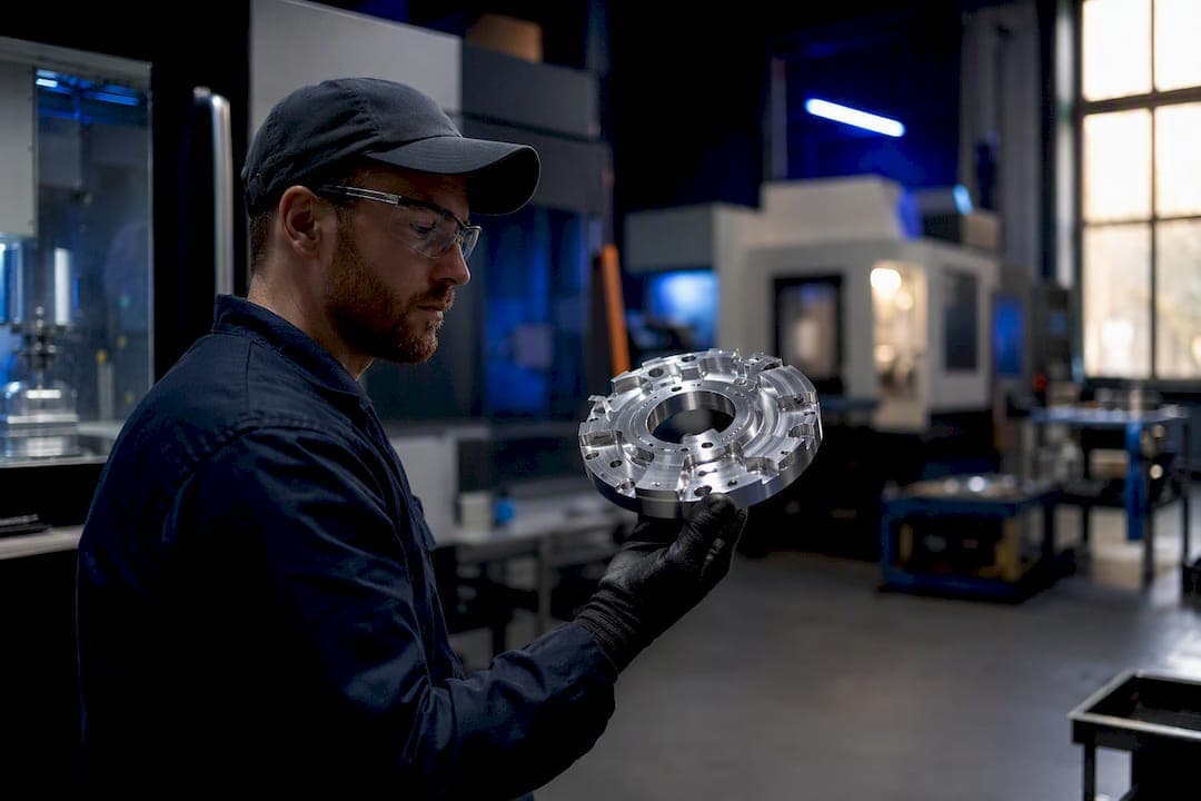
Run a separate finishing pass at reduced feed with a larger nose radius or wiper insert, and you'll fix most surface finish problems before touching anything else. That single change addresses the biggest lever in the whole process: feed rate. Everything else on this list matters, but it's secondary.
Work through these in order before you start swapping tooling or blaming the machine:
- Reduce finishing feed rate below your roughing feed, keeping chipload reasonable for the insert.
- Check spindle runout and tramming. A 0.002-inch runout wrecks a perfect feed calculation.
- Tighten workholding. Any flex under cutting load shows up as waviness.
- Clear chips aggressively. Recut chips scratch and drag across the surface.
- For contoured or 3D work, tighten stepover to shrink scallop height.
After each change, measure Ra on a test coupon rather than eyeballing it.
Key Takeaways
Surface finish improves fastest when feed rate, nose radius, and machine rigidity are corrected in that order, verified by measurement rather than assumption.
| Point | Details |
|---|---|
| Fix feed first | Feed rate has the largest effect on theoretical roughness; reduce it before changing tooling or the machine. |
| Separate roughing and finishing | Leave 0.010 to 0.020 inches of stock and run a distinct, lighter finishing pass. |
| Rule out mechanical causes | Runout, poor tram, and excess tool stickout create defects no feed change will fix. |
| Match measurement to the spec | Ra, Rz, and RMS aren't interchangeable; use the correct cutoff length and measure what the drawing calls out. |
| Use calculators to skip guesswork | Availzyemachinistpro's Surface Finish Calc and Job Tracker turn one good test result into a repeatable process. |
Table of Contents
- Prioritized Shop Checklist To Improve Surface Finish
- What Do Ra, Rz, and RMS Actually Mean?
- How Do Feeds, Speeds, and Tool Geometry Set Your Finish?
- Fixing Mechanical Causes: Runout, Tram, and Chatter
- Setting Stepover for Milled and Contoured Surfaces
- Which Post-Process Gets You to a Specific Ra Target?
- Using Small Experiments to Predict Finish Instead of Guessing
- Surface Finish Symptom-to-Fix Reference
- The Real Tradeoff Behind Every Finish Spec
- Tools That Speed Up Surface Finish Work
- Sources
Prioritized Shop Checklist To Improve Surface Finish
Trial-and-error burns tool life and material. Work this sequence instead, and check results before moving to the next step.
First: separate roughing from finishing. Leave 0.010 to 0.020 inches of stock for a dedicated finishing pass. Roughing parameters chew through material fast and leave a torn surface; finishing parameters need a completely different feed and depth of cut. Running one pass to do both jobs is the single most common mistake in home shops.

Second: dial in feed rate. Lower feed reduces the cusps left between each tool pass, but going too low backfires. Below a certain threshold, edge geometry and machine precision start to dominate the surface rather than feed itself, and finish stops improving or gets worse from rubbing instead of cutting. A reasonable starting range for finishing steel or aluminum is a low feed rate in turning, adjusted for insert nose radius, to reduce surface roughness.
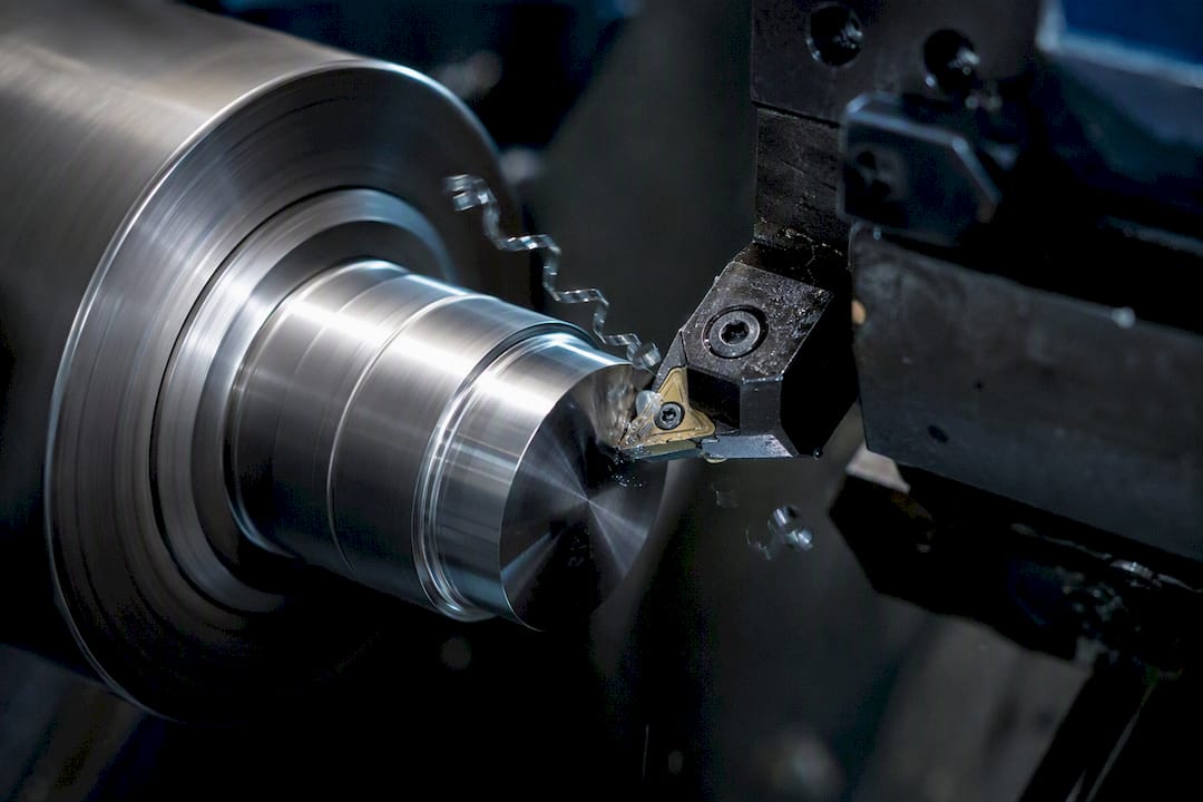
Third: bump the nose radius or switch to a wiper insert. A larger radius smooths the theoretical scallop between passes, and wiper geometry lets you run higher feed for the same finish. The tradeoff is deflection risk on thin-walled parts, so do not oversize the radius on flexible workpieces.
Fourth: match SFM and coolant to material. Aluminum tolerates higher speed and thrives with flood coolant. Stainless needs slower surface speed and steadier feed to avoid work hardening. On interrupted cuts, coolant can actually hurt the finish by thermally shocking the edge. Air blast often outperforms flood coolant there.
Fifth: check workholding and toolholding before touching parameters again.
Sixth: run a spring pass. Repeat the final finishing pass with zero programmed additional depth. It removes deflection artifacts the first pass couldn't catch, according to a widely used CNC finishing workflow.
Pro Tip: Run the spring pass twice on anything held in a three-jaw chuck. The second pass often reveals whether your first "improvement" was real or just a lucky measurement.
What Do Ra, Rz, and RMS Actually Mean?
Ra averages the roughness profile; Rz measures peak-to-valley height across sampling lengths; RMS (technically Rq) squares and averages the deviations. They are not interchangeable, and treating them as the same number gets people in trouble on inspection reports.
Rough conversion heuristics exist, but they're heuristics, not physics:
- Rz typically runs 4 to 7 times the Ra value, depending on the process and profile shape.
- RMS runs roughly 1.11 times Ra for most machined surfaces.
- Never substitute one for another on a drawing callout. Measure the parameter actually specified.
Cutoff length (λc) matters more than most people realize. A profilometer trace with the wrong cutoff length filters out or includes waviness that shouldn't be there, skewing the number. ISO 4288 and ASME B46.1 both specify cutoff lengths based on expected roughness range, so match your instrument setting to the target finish before you trust the readout.
Quick reference: Ra 3.2 µm (125 µin) is a typical as-milled or as-turned default. Ra 1.6 µm (63 µin) needs a dialed-in finishing pass. Ra 0.8 µm (32 µin) usually requires grinding, polishing, or a very controlled finishing operation, per common Ra-to-process mapping. For a deeper breakdown of these bands, see this Ra vs Rz guide.
How Do Feeds, Speeds, and Tool Geometry Set Your Finish?
Turning and milling both follow a kinematic relationship between feed, tool nose radius, and theoretical roughness: Ra ≈ f²/(32·r), where f is feed per revolution and r is nose radius. Double the feed and roughness quadruples. Double the nose radius and roughness is cut in half. Feed dominates the equation, which is why it's the first knob every experienced machinist touches.
That formula predicts theoretical roughness only. Real parts usually come in 20 to 40% rougher than the calculation suggests, thanks to vibration, tool wear, and material behavior the equation ignores. Use the formula to pick a starting point, then verify with a real measurement.
Practical feed ranges for a decent finish in turning:
- Ra 1.6 µm target: roughly 0.003 to 0.005 ipr with a 1/32-inch nose radius.
- Ra 0.8 µm target: roughly 0.001 to 0.003 ipr, often paired with a wiper insert to hold cycle time.
- Below a certain feed floor, Rz stops improving with feed and becomes limited by machine precision and insert edge sharpness instead.
Wiper inserts spread the same geometric benefit as a bigger nose radius across a longer contact length, letting you run higher feed without paying the roughness penalty. Fine-edge carbide, PVD-coated grades, and cermet inserts hold a sharper edge longer, which matters most on stainless and other work-hardening alloys where a dulling edge degrades finish fast. Aluminum is forgiving; you can push higher feed and speed and still land a clean finish. Stainless punishes the same aggression with smearing and built-up edge, so drop feed and surface speed together rather than compensating with one alone.
Fixing Mechanical Causes: Runout, Tram, and Chatter
Parameter tweaks hit a wall when the machine itself is the problem. Spindle runout above roughly 0.001 inch shows up as an uneven finish no feed adjustment will fix, so check it with a dial indicator on a ground test bar before chasing anything else. A dirty or worn collet is the most common culprit, and it's a five-minute fix.
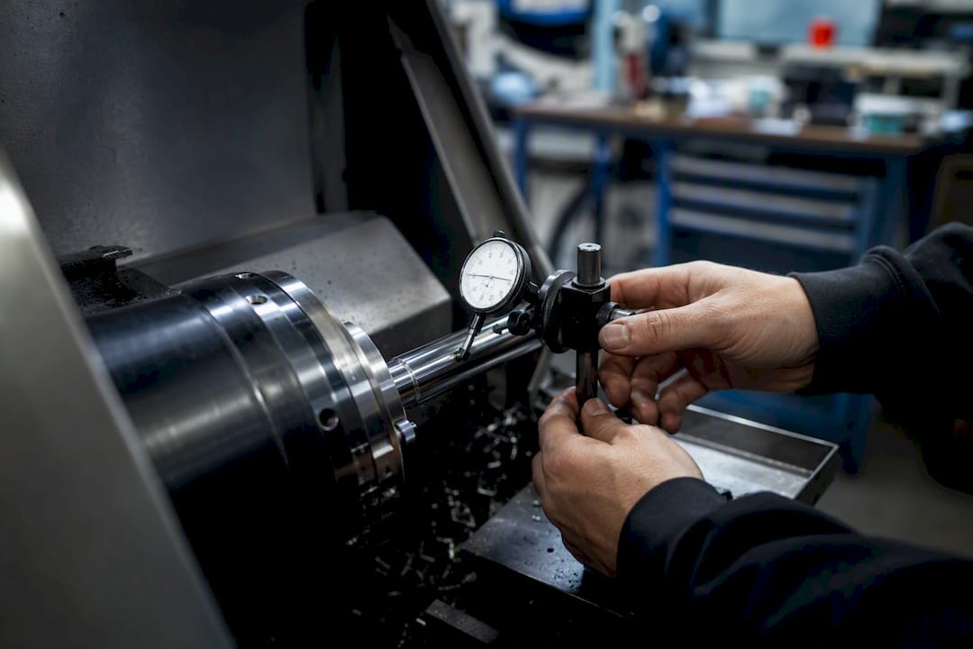
Tramming matters as much on a router or mill as runout does on a lathe. An untrammed spindle cuts a stepped or tapered surface across a wide face, and no amount of finishing passes evens that out. Check tram after any tooling change on gantry-style machines, and resurface the spoilboard if it's been trammed out for a while.
Work through these before touching feed again:
- Inspect toolholder seats and pockets for wear. A sloppy fit reintroduces runout even with a straight tool.
- Minimize tool stick-out. Every extra quarter-inch of overhang multiplies deflection.
- Check clamping points for flex under load, especially on thin-walled or long parts.
- Redesign the fixture if repeated chatter marks trace back to workpiece movement rather than tool deflection.
Chatter announces itself with a distinct ripple pattern and often an audible chirp or squeal. The fastest fix is reducing radial engagement or spindle speed slightly, off the resonant frequency. If it persists across multiple jobs, a damped toolholder solves what parameter changes can't.
Pro Tip: Run a coin test. Set a coin on the machine bed during a cut. If it dances, you've got a vibration problem no feed adjustment will solve.
Setting Stepover for Milled and Contoured Surfaces
Ball-nose finishing on contoured surfaces follows its own geometry. Scallop height between passes relates to stepover and tool radius by h = s²/(8·r), where s is stepover and r is the ball radius. Cut stepover in half and the visible scallop drops to a quarter of its original height.
For show surfaces, keep stepover at 10% of cutter diameter or less. Going tighter than that buys diminishing returns for a lot of extra cycle time, since scallop height already drops fast as stepover shrinks.
- Climb milling produces a cleaner shear cut on the finish pass and reduces the tearing you get from conventional milling on softer materials.
- A smaller-diameter finish cutter lets you run tighter stepover without exploding cycle time, but it costs some rigidity.
- Constant scallop height toolpaths and adaptive finishing strategies in CAM automatically vary stepover across curvature, holding a consistent finish on complex surfaces where fixed stepover would under- or over-cut in different regions.
- Run a light finishing pass separate from roughing here too. The same principle from turning applies to milling.
Which Post-Process Gets You to a Specific Ra Target?
Machining alone has limits. When a print calls for a mirror finish or a sub-8 microinch Ra, post-processing usually beats chasing it with cutting parameters alone.
| Process | Typical Ra range | Best suited for |
|---|---|---|
| As-machined finishing pass | 32 to 125 µin | General mechanical fits, non-critical surfaces |
| Grinding or honing | Under 8 to 32 µin | Bearing bores, precision shafts, hardened steel |
| Wet sanding / hand polishing | 4 µin | Molds, cosmetic aluminum, plastic tooling |
| Media/bead blasting | matte finish (not reducing Ra) | Cosmetic uniformity, not smoothness |
| Electropolish | Under 10 µin | Stainless, medical and food-grade parts |
Grit progression matters for wet sanding: step through grits gradually rather than skipping, and know whether your abrasive is rated on the FEPA or CAMI scale, since the same grit number means a different actual particle size between the two. Media blasting deserves a caution here: it creates a uniform matte look but doesn't lower Ra the way people assume, and in some cases it roughens the surface. Electropolish works well on stainless for medical and food-contact parts, but it removes material unevenly on complex geometry unless anode placement is dialed in, an area where a specialized anodizing and finishing optimization service earns its fee. Machine finishing is almost always cheaper than a secondary process when the tolerance allows it. Reserve post-processing for the Ra bands machining genuinely can't reach economically.
Using Small Experiments to Predict Finish Instead of Guessing
Feed rate isn't just the biggest lever, it's usually the only variable worth testing carefully. A 2023 turning study using the Taguchi method confirmed feed dominates surface roughness outcomes and found feed rates under 0.3 mm/rev produced the best results in that experiment's material and tooling setup.
A practical workflow: pick two or three suspect variables (feed, speed, stickout), run a small nine-run test grid on a scrap coupon, measure Ra on each, then feed those results into a calculator to predict your production setting rather than guessing at the next job.
Small, structured experiments beat broad parameter hunts because they isolate which variable actually moved the needle, instead of changing three things at once and hoping one of them was the fix.
Log every test run somewhere you'll actually find it again. A Job Tracker tied to tool-deflection and chatter prediction turns a one-off good result into a repeatable process instead of a lucky accident.
Surface Finish Symptom-to-Fix Reference
Match what you're seeing to the likely cause before changing anything else.
| Symptom | Probable cause | Immediate fix |
|---|---|---|
| Chatter ripples | Vibration or excess overhang | Reduce engagement, shorten stickout |
| Visible scallops | Stepover too wide | Tighten stepover, use ball-nose finish pass |
| Concentric rings (turning) | Feed too high or worn insert | Reduce feed, check insert edge |
| Dragged or smeared surface | Dull edge or wrong coolant strategy | Replace insert, switch to air blast |
| Scratches from recut chips | Poor chip evacuation | Increase coolant flow or air blast, clear chips |
Measure Ra after each fix and log the result. Guessing your way through two changes at once erases the diagnostic value of the test.
The Real Tradeoff Behind Every Finish Spec
Every step down in Ra costs you cycle time, tooling, or a secondary process, and most drawings specify a tighter finish than the part actually needs. That's not laziness on the machinist's part. It's usually a designer defaulting to a "safe" callout without pricing out what it costs to hit.
Specify the coarsest finish that still does the job functionally, then reserve the tight tolerances for surfaces that genuinely need them, like sealing faces or bearing bores. The measure-correct-measure cycle beats a broad parameter hunt every time, and a disciplined small experiment gets you to a stable process faster than an afternoon of random tweaking. Software that logs your settings and results turns a one-time success into something you can hand off to someone else on the shop floor without repeating the whole diagnostic process.
— Availzye
Tools That Speed Up Surface Finish Work
Diagnosing finish problems by hand works, but it's slow, and every recalculation by hand is a chance to drop a decimal. Availzyemachinistpro's Surface Finish Calc converts between Ra, Rz, and RMS and back-solves feed and nose radius for a target finish, so you skip the manual algebra entirely. Pair it with the Feeds & Speeds calculator to check chipload before you cut, and the Tool Deflection calculator to catch stickout problems before they show up as chatter on the part.
The Job Tracker logs every test run and setting change against the actual coupon result, so a good finish from three months ago is searchable instead of forgotten. Availzyemachinistpro runs three tiers: Individual at $9.99 a month, Small Shop at $24.99, and Team at $49.99, all with a 7-day free trial. Run your next coupon test during the trial and see whether the calculated feed matches what actually comes off the machine before you commit to a subscription. Start with the Surface Finish Calc and work backward from your target Ra.
Sources
- Achievable Surface Finishes by Machining Process: Turning, Milling, Boring, Grinding | Industry Resource Center
- CNC surface finish optimization: Cut It Clean