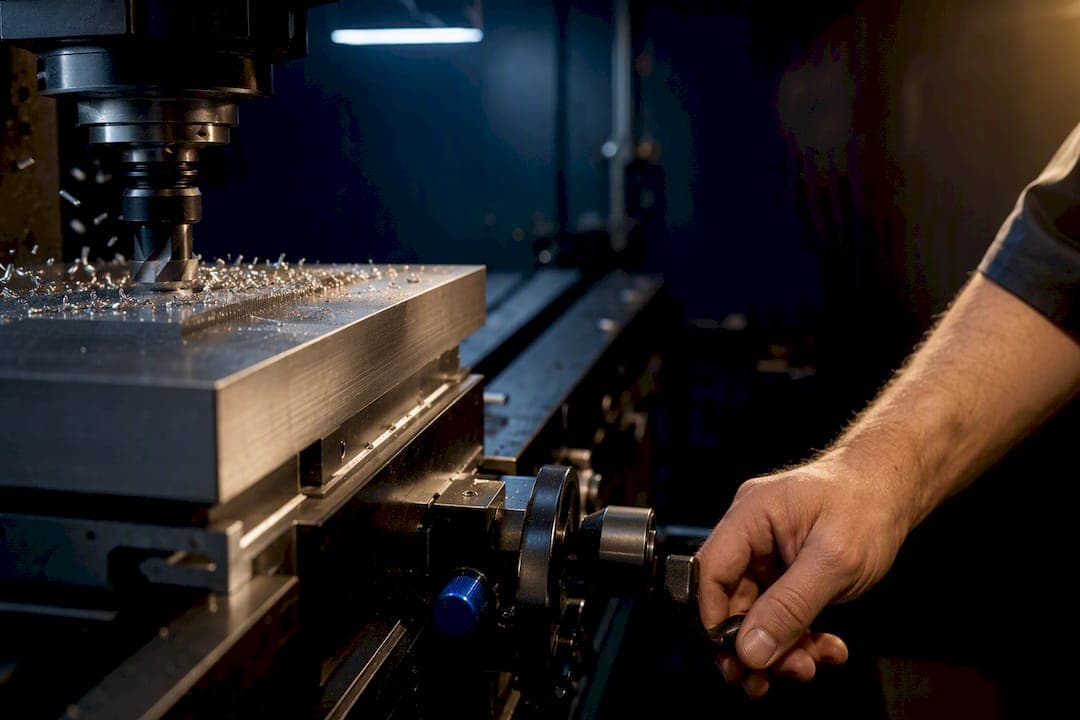
Start with the tool maker's SFM, convert it to RPM, pick the recommended chip load, calculate feed rate, then run a test cut on scrap. That sequence, in that order, is what actually prevents rubbing, chatter, and snapped end mills. The formulas below run on constants from Machinery's Handbook, and a calculator like Availzye Machinist Pro can automate the math, but the workflow itself matters more than the tool you use to run it.
TL;DR:
- Tool manufacturers recommend starting at lower speeds and feeds for machines with less rigidity, such as hobby routers, to prevent tool breakage or chatter.
- Correct for chip thinning when radial engagement falls below 50% of the tool diameter to maintain proper chip load and avoid rubbing or excessive wear.
- Recording successful cutting parameters and running test cuts on scrap stock are essential steps before committing to full production, especially when using automated calculators.
- Use specific, proven formulas for RPM and feed rate calculations, adjusting based on material and tooling used, rather than relying solely on calculator outputs.
- Prioritize conservative settings and thorough validation on the production floor to ensure the repeatability and reliability of each machining process.
Table of Contents
- Feeds and Speeds Fundamentals: SFM, RPM, Feed Rate, Chip Load, DOC, and WOC
- Core Formulas for Turning, Milling, and Drilling: RPM, Feed Rate, and MRR
- How to Use a Feeds-and-Speeds Calculator (and What to Enter)
- Chip Thinning: Why Low Radial Engagement Ruins Your Feed Rate
- Starting Settings for Aluminum, Steel, Stainless, and Wood
- Feeds and Speeds Troubleshooting: Matching Symptoms to Fixes
- Climb Milling, HEM, and Chatter: Advanced Techniques That Change the Math
- Turning Calculation Into a Repeatable Shop Workflow
- Priorities Shift Between the Hobby Bench and the Production Floor
- Run Your Numbers, Then Cut Real G-Code With Availzye Machinist Pro
- Sources
- FAQ
Feeds and Speeds Fundamentals: SFM, RPM, Feed Rate, Chip Load, DOC, and WOC
Every feeds and speeds calculation rests on a handful of variables, and once you understand what each one physically does, the formulas stop feeling like arbitrary math.
Surface speed (SFM or Vc) is how fast the cutting edge moves through the material, measured in surface feet per minute (or meters per minute outside the US). This number comes from the tool and material, not from your machine. A carbide end mill in aluminum tolerates a much higher SFM than the same tool in stainless steel, because aluminum generates less friction and heat at the cutting edge.
RPM is what your spindle actually dials in. SFM is the target; RPM is how you get there once you know the tool's diameter.
Feed rate is how fast the tool travels through the material, expressed in inches per minute (IPM). It's a function of RPM, flute count, and chip load, not something you set independently.
Chip load (IPT), feed per tooth, is arguably the most important number in the whole system. It's the thickness of the chip each cutting edge removes on a single pass. Too thin, and the edge rubs instead of cutting, generating heat that dulls the tool. Too thick, and you overload the flute, which can chip the edge or stall the spindle.
Depth of cut (DOC) and width of cut (WOC, also called radial engagement) describe how much material the tool engages axially and radially. Together with feed rate, these define your material removal rate (MRR), calculated as feed rate multiplied by WOC multiplied by DOC.
A few relationships worth internalizing before you touch any calculator:
- Higher SFM and thinner chip loads generate more heat relative to mechanical stress on the tool.
- Lower SFM and heavier chip loads shift the load toward mechanical stress, which is easier on carbide but harder on a weak machine.
- MRR governs cycle time, but pushing MRR too far sacrifices tool life, and a snapped $40 end mill erases any time you saved.
- Chip load scales with tool diameter, larger tools can absorb heavier chips per tooth without added stress on any single flute.
The balance between heat and mechanical load is the whole game. Every adjustment you make, feed, speed, depth, is really just shifting that balance one direction or the other.
Core Formulas for Turning, Milling, and Drilling: RPM, Feed Rate, and MRR
Three formulas cover the vast majority of feeds and speeds calculations across turning, milling, and drilling operations. Learn these and you can sanity-check any calculator's output by hand.
1. RPM from surface speed: RPM = (SFM × 3.82) ÷ Tool Diameter (inches)
The constant 3.82 comes from converting feet to inches and accounting for the circumference formula (π), a derivation documented in Machinery's Handbook and consistent across tooling manufacturer data. In metric, the equivalent is RPM = (Vc × 1000) ÷ (π × diameter in mm).
2. Feed rate from RPM, flutes, and chip load: Feed Rate (IPM) = RPM × Number of Flutes × Chip Load (IPT)
3. Material removal rate: MRR (in³/min) = Feed Rate × Width of Cut × Depth of Cut
Here's a worked example using a 3/8 inch, 2-flute carbide end mill cutting 6061 aluminum. The tool manufacturer recommends 600 SFM and a 0.004 inch chip load for this diameter.
Round the RPM down to whatever your spindle can hit cleanly, most routers and benchtop mills don't offer stepless control up to 6,112, so you'd dial in 6,000 and recalculate feed rate to match:
- Confirm actual spindle RPM (6,000 in this case).
- Recalculate feed rate: 6,000 × 2 × 0.004 = 48 IPM.
- Check MRR against your machine's horsepower and rigidity limits.
- Run the cut on scrap stock and inspect the chips before committing to a full program.
That last step matters more than the formulas themselves. A calculated number is a starting hypothesis, not a guarantee, and the full formula walkthrough is worth bookmarking for jobs that don't match this exact example.
How to Use a Feeds-and-Speeds Calculator (and What to Enter)
A calculator only outputs good numbers if you feed it the right inputs. At minimum, any reliable cutting speed calculator needs:
- Material grade (6061-T6 aluminum behaves differently than cast aluminum, and 304 stainless cuts nothing like 4140 steel)
- Tool diameter, flute count, and coating (TiAlN coatings tolerate higher heat than uncoated carbide)
- Depth of cut and width of cut for the specific pass
- Your machine's maximum RPM and available torque at that RPM
Manufacturer recommendations sometimes conflict with each other, one catalog might list 500 SFM for a tool where another suggests 700. When that happens, start at the lower number. You can always increase feed and speed on the next pass once you've confirmed the tool isn't rubbing or chattering, but you can't un-break a tool that got pushed too hard on the first cut.
What no calculator can know is your specific machine's condition. It doesn't know if your gantry has 0.010 inches of backlash, whether your vise is gripping the stock securely, or if that particular end mill has been reground and now runs 0.002 inches out of true. Those variables shift the safe operating window, sometimes significantly, and only a physical test cut reveals them.
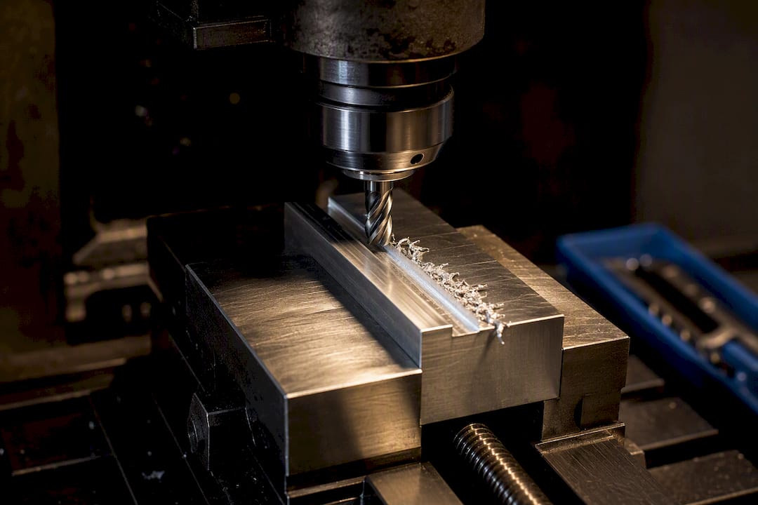
Pro Tip: Keep a written log of every setting that worked on a given material and tool combination. Six months from now, you won't remember that 0.005 IPT was the sweet spot for that specific 1/4 inch upcut spiral in Delrin, but a shop notebook will.
Chip Thinning: Why Low Radial Engagement Ruins Your Feed Rate
When your radial engagement drops below roughly 50% of the tool's diameter, the chip you're actually cutting gets thinner than the chip load you programmed, even though the math says otherwise. This matters constantly in modern toolpaths, because trochoidal and adaptive clearing strategies deliberately run light radial engagement to reduce heat and tool deflection. Without a correction, the tool spends most of its time rubbing instead of cutting cleanly, which accelerates wear fast.
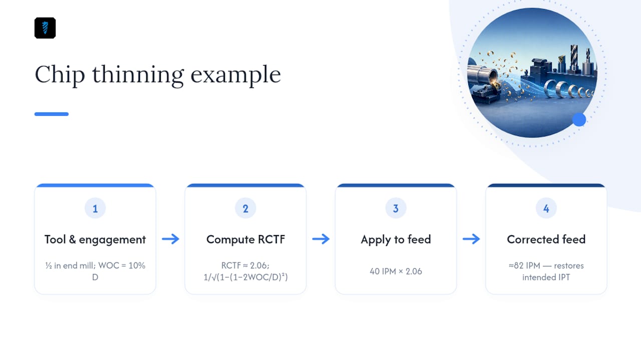
The fix is the radial chip thinning factor (RCTF). At low engagement, you increase programmed feed rate to compensate, so the actual chip thickness still matches your intended IPT.
RCTF = 1 ÷ √(1 − ((1 − 2 × WOC/D)²))
Where WOC is your radial width of cut and D is tool diameter. You multiply your calculated feed rate by this factor to get the corrected feed.
Take a 1/2 inch end mill running a trochoidal path at 0.05 inch radial engagement, that's 10% of diameter. Without correction, a calculated feed rate of 40 IPM would leave the tool rubbing most of the cut. Apply the RCTF of roughly 2.06, and the corrected feed rate becomes about 82 IPM, which restores the intended chip thickness at that shallow engagement.
Pro Tip: If you're running adaptive clearing in a CAM package like Fusion 360 or Mastercam, check whether the software already applies chip thinning automatically. Many do, and manually correcting again on top of that will overfeed the tool. For a deeper dive into the math, the chip load formula guide covers edge cases like ball-nose engagement that this section doesn't.
Starting Settings for Aluminum, Steel, Stainless, and Wood
Every machine class needs its own starting point, and the gap between a hobby router and a rigid VMC is wider than most beginners expect. These tiers assume a 1/4 inch, 2-flute carbide end mill as the baseline; scale feed rate proportionally for other diameters and flute counts using the core formulas above.
| Material | Tier | DOC | Stepover (WOC) |
|---|---|---|---|
| Aluminum (6061) | Conservative | small | low |
| Aluminum (6061) | Normal | moderate | moderate |
| Aluminum (6061) | Aggressive | larger | higher |
| Mild steel | Conservative | small | low |
| Mild steel | Normal | moderate | moderate |
| Stainless (304) | Conservative | very small | minimal |
| Stainless (304) | Normal | small to moderate | low to moderate |
| Wood (hardwood) | Normal | moderate to large | higher |
| Plastics (Delrin/HDPE) | Normal | moderate | moderate |
Aluminum tolerates dramatically higher SFM and chip loads than steel because it generates far less cutting heat per unit of material removed, which is why carbide tooling stays sharp at 800 SFM in aluminum but would burn up almost instantly at that speed in stainless.
A few scaling rules to keep in your back pocket:
- Larger diameter tools can run proportionally higher feed rates at the same chip load, since feed rate scales linearly with flute count and IPT, not diameter directly.
- A router-class machine (think a hobby CNC router with a trim router spindle) has far less rigidity and torque than a rigid mill, so treat every number above as a starting ceiling on a router-class machine, not a floor.
- Reduce depth of cut before you reduce chip load if you're hearing chatter, changing DOC affects tool deflection more directly than IPT does.
- Wood and plastics tolerate aggressive feed rates but need faster chip evacuation, dust collection or air blast matters as much as the numbers themselves.
The practical protocol, regardless of material, is always the same: start conservative, run the cut on scrap stock, inspect the chips and the finish, then nudge feed upward in small increments while logging what works.
Feeds and Speeds Troubleshooting: Matching Symptoms to Fixes
Chip appearance tells you more than any calculator ever will. Aluminum should curl into small commas or spirals; if you're getting fine powder or dust instead, something's wrong before you even look at the surface finish.
| Symptom | Likely Cause | Corrective Action |
|---|---|---|
| Squealing, burning smell, powdery chips | Chip load too low, tool is rubbing | Increase feed rate or reduce RPM |
| Loud chatter, rippled surface finish | Feed too aggressive for setup rigidity, or resonant RPM | Reduce RPM slightly, or increase chip load and slow feed |
| Tool chipping or breaking at the tip | Excessive feed, runout, or workholding movement | Check runout first, then reduce feed before touching RPM |
| Poor surface finish, visible tool marks | Stepover too large, or dull/worn tool | Reduce stepover, inspect edge wear under magnification |
| Long stringy chips that won't clear | Feed too low relative to depth in aluminum | Raise feed rate, check chip evacuation (air/coolant) |
| Discolored chips (blue/purple in steel) | Excess heat from friction | Reduce SFM, or add cutting fluid |
The general rule most machinists follow: adjust feed rate before RPM when the problem is heat or finish, and check runout and workholding first when the problem is breakage. A tool that snaps clean at the flute usually means excessive feed or a loose collet, not the wrong SFM. For finish problems specifically, the surface finish guide walks through stepover math and scallop height in more depth than a troubleshooting table can.
Climb Milling, HEM, and Chatter: Advanced Techniques That Change the Math
Climb milling versus conventional milling isn't just a preference, it changes your effective feeds and speeds. In climb milling, the cutter rotates in the same direction as the feed, which reduces friction, improves surface finish, and extends tool life on a rigid CNC setup. Conventional milling, where the cutter rotates against the feed direction, becomes the safer choice on manual mills with backlash, since climb milling on a loose machine can let the cutter grab and pull the workpiece into the tool.
High-efficiency milling (HEM) and adaptive clearing flip the traditional feeds and speeds mindset. Instead of a heavy radial cut at low RPM, you run very light radial engagement (often under 10% of diameter) at a much higher feed rate, distributing wear across the entire flute length rather than concentrating it at the tip. This only works with proper chip thinning correction, without it, you're back to rubbing instead of cutting. The HEM technical guide covers toolpath strategy specifics beyond what fits here.
Chatter mitigation follows a short checklist when it shows up:
- Change spindle RPM by 10 to 15% in either direction to move off a resonant frequency.
- Increase chip load rather than decreasing it, counterintuitively, a thicker chip per tooth is often more stable than a thin, rubbing one.
- Add physical stiffness where you can, shorter tool stickout, better workholding, a stiffer fixture.
- Monitor spindle load if your machine displays it, a sudden spike often precedes a chatter event or tool failure.
Pro Tip: If chatter appears only at certain depths within a single pocket, suspect harmonic resonance tied to stickout length, not your feeds and speeds numbers at all. Shortening the tool in the holder sometimes fixes what no amount of RPM tweaking will.
Turning Calculation Into a Repeatable Shop Workflow
Running the math by hand works fine for one job. It breaks down fast when you're cutting a dozen different tools across a dozen materials in the same week, which is where a structured workflow earns its keep.
The calculation-to-record pipeline looks like this in practice:
- Correct: Apply the RCTF if your toolpath runs light radial engagement, adaptive or trochoidal strategies need this step almost every time.
- Cross-check: Reference the tool's entry in a tool database to confirm coating limits and prior performance on similar jobs.
- Test: Run the corrected numbers on scrap stock, inspect chip formation and finish.
- Log: Record what worked in a job tracker tied to that specific tool and material combination, so the next operator running the same job doesn't start from zero.
That last step is the one most shops skip, and it's the one that saves the most time over a year. A setup that took twenty minutes of trial and error the first time should take zero minutes the second time, if the settings got written down somewhere searchable instead of scribbled on a sticky note that gets thrown away.
If your shop tracks credentials, third-party tooling endorsements, or documented case studies from specific jobs, that record belongs right here, next to the numbers that produced it. Verified results carry more weight than any calculator output on its own.
Priorities Shift Between the Hobby Bench and the Production Floor
Hobbyists and production shops are solving different problems even when they're running the same formulas. If you're machining in a garage on a benchtop mill, the priority is conservative settings, disciplined test cuts, and a logbook you actually update. You have one machine and a limited tool budget, so a broken end mill costs you a trip to the hardware store and a lost evening, not a missed customer deadline.
Production shops face a different risk profile entirely. The real work is in validation: documented setup sheets, repeatable workholding, and some form of spindle load or vibration monitoring on jobs that run unattended overnight. A setting that works once on a test cut needs to work a thousand times in a row without a supervisor watching.
Neither group benefits from chasing the absolute top of the feed and speed range. The fastest setting that survives exactly one part isn't a setting worth keeping, it's a setting worth debugging.
— Availzye
Run Your Numbers, Then Cut Real G-Code With Availzye Machinist Pro
Everything in this guide, the SFM-to-RPM conversion, the RCTF correction, the chip load logging, runs faster when the calculator and your job records live in one place instead of scattered across spreadsheets and sticky notes. Availzye Machinist Pro pairs the feeds and speeds calculator with a tool database, chip thinning math, and a job tracker, so the setting that worked on Tuesday is still findable in March.

Once you've calculated a feed rate and depth of cut that survives a test cut, the next bottleneck is usually turning that into clean, validated toolpaths. The G-code generator takes your calculated parameters and produces machine-ready code without a separate manual translation step. Start the 7-day free trial and run your next job's numbers through the full workflow before you commit a single real part to the vise.
Sources
A few sources are worth bookmarking beyond this guide, especially when you're calculating for a material or operation not covered above.
- CNC Feeds & Speeds Guide
- Speeds and feeds — Wikipedia
- Climb milling vs conventional milling
- Feeds and speeds calculator guide for CNC professionals
FAQ
How Do You Figure Out Speeds and Feed for a Job?
Convert the tool manufacturer's recommended SFM to RPM using RPM = (SFM × 3.82) ÷ diameter, then calculate feed rate as RPM × flutes × chip load, and validate on scrap before running the full job.
What Is the Best Tool for Calculating Feed and Speed?
A dedicated calculator that also lets you log results and cross-check tool data, like Availzye Machinist Pro's feeds and speeds tool, saves time over recalculating by hand for every new tool and material combination.
What Are Good Feeds and Speeds for a CNC Router?
Router-class machines have less rigidity than a rigid mill, so start at the conservative end of any chart, roughly 400 SFM and 0.002 inch chip load for a 1/4 inch end mill in aluminum, and scale up only after a clean test cut.
What Is a Good Feed and Speed for Aluminum?
For a 1/4 inch, 2-flute carbide end mill in 6061 aluminum, 600 SFM with a 0.004 inch chip load is a solid normal starting point, yielding roughly 9,780 RPM and a feed rate near 78 IPM before any chip thinning correction.
When Do I Need to Correct for Chip Thinning?
Apply a radial chip thinning correction whenever your radial engagement drops below about 50% of tool diameter, which is standard practice in trochoidal and adaptive clearing toolpaths.