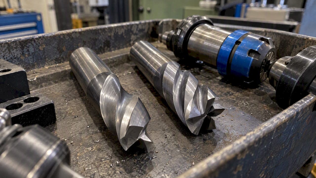
Feed per tooth (Fz) is the chip load each cutting edge removes, measured in inches or millimeters per tooth. Feed per revolution (fr) equals Fz multiplied by the number of teeth, and table feed (Vf) equals that result multiplied by RPM. The practical rule: set your target Fz first, then convert it to the feed rate your controller actually runs.
TL;DR:
- Multiply the toolmaker’s Fz by flute count to get feed per revolution, then multiply by RPM for table feed in G94.
- At 16.7% radial engagement, a 12 mm, four flute cutter needs about a 1.34 correction; 0.05 mm Fz yields roughly 805 mm/min at 3,000 RPM.
- When radial engagement falls below roughly 20% of cutter diameter, chip thinning can make actual chips too thin, causing rubbing, heat, and faster edge wear.
- Use G94 for feed per minute and G95 for feed per revolution, and verify that CAM output, controller units, and actual flute count agree.
Table of Contents
- What Feed per Tooth and Feed per Revolution Actually Mean
- How to Calculate Feed per Tooth, Feed per Rev, and Table Feed
- Why Actual Chip Thickness Rarely Matches Programmed Fz
- Correcting for Chip Thinning: RCTF Step by Step
- Worked Examples: Fz to Fr to Table Feed
- Common Mistakes When Setting Milling Feeds
- How We Approach Feed Calculations at Availzye
- Try the Feeds and Speeds Calculator for Your Next Job
- FAQ
- Sources
What Feed per Tooth and Feed per Revolution Actually Mean
Feed per tooth (Fz) describes how much material one cutting edge shaves off during a single pass, expressed in inches per tooth (ipt) or millimeters per tooth. Feed per revolution (f or fr) is the distance the tool advances during one full spindle rotation, in inches per revolution (ipr) or mm/rev. Table feed (Vf) is what the machine actually executes, in inches per minute (ipm) or mm/min, and it depends on spindle speed (n, in RPM) and the number of cutting edges (Z).
Toolmakers publish Fz because it reflects the load a single edge sees, which drives tool wear regardless of flute count or RPM. Programmers often think in table feed because that's what the controller displays and what the machine follows in real time.
- Fz: chip load per edge (ipt or mm/tooth), set from tooling data
- fr: feed per revolution (ipr or mm/rev), equals Fz × Z
- Vf: table feed (ipm or mm/min), what the spindle actually executes
- G95 mode asks for feed per revolution; G94 asks for feed per minute, per common programming conventions
How to Calculate Feed per Tooth, Feed per Rev, and Table Feed
The relationship between these three values follows a fixed chain, and once you know it, converting between them takes seconds.
- Start with Fz from your tool manufacturer's data sheet, the per-edge chip load for your material and tool diameter.
- Multiply Fz by the number of flutes (Z) to get feed per revolution: f = fz × Z.
- Multiply that result by spindle RPM (n) to get table feed: Vf = f × n = fz × Z × n.
- Calculate RPM from cutting speed using RPM = (SFM × 3.82) / diameter for inch units, a formula confirmed in Haas programming references.
- Enter the final Vf value into the controller if it's running in G94, or enter fz × Z directly if the control supports a per-rev mode.
These formulas match the standard definitions laid out in Iscar's milling cutter reference guide, which treats fz as the per-edge parameter and Vf as its full downstream product.
Haas confirms that IPM equals feed per tooth multiplied by tooth count multiplied by RPM, which is the single formula that ties every other number in this chain together.
Unit consistency matters more than the math itself. Mixing metric Fz with an inch-based RPM formula, or forgetting that a 4-flute tool at 0.004 ipt produces a very different table feed than a 2-flute tool at the same Fz, causes most feed rate errors on the shop floor. Confirm whether your CAM software outputs fz or Vf before you post the program, since some post-processors silently convert one to the other.
Why Actual Chip Thickness Rarely Matches Programmed Fz
The chip load you program and the chip thickness the edge actually experiences are not always the same number. When a cutter engages only part of its diameter radially, as it does in most slotting and profiling passes, the actual chip thickness (h) drops below the programmed Fz because the edge sweeps through a shorter arc of material.
Effective diameter compounds this. A ball-nose end mill cutting at a shallow depth engages only a small effective diameter near its tip, which changes both the real cutting speed and the resulting chip thickness compared to what a flat-based RPM calculation assumes. Entering angle has a similar effect: a 45 degree lead angle spreads the same Fz over a longer edge contact, thinning the chip further.
- Partial radial engagement reduces actual chip thickness below programmed Fz
- Ball-nose and profile cutters need effective diameter, not nominal diameter, for accurate RPM
- A shallow entering angle spreads chip load thinner across the edge
- Thin chips cause rubbing instead of shearing, which accelerates edge wear on coated tools
Rubbing instead of clean shearing generates excess heat at the cutting edge, which is particularly damaging to coated carbide tools designed to shear, not scrape. The visible result on the part is often a poorer surface finish than the programmed feed should produce, since the edge is dragging rather than cutting cleanly. This exact gap between programmed feed and real chip thickness is a core theme in HEM strategy, where light radial engagement is the entire point.
Pro Tip: Check your radial engagement percentage before trusting a textbook Fz value: anything under roughly 20% of cutter diameter usually needs a chip-thinning correction.
Correcting for Chip Thinning: RCTF Step by Step
The radial chip-thinning factor (RCTF) adjusts your target Fz upward so the cutting edge still sees the chip thickness you intended, even at partial radial engagement. FM Carbide's chip load reference shows this clearly: a 12 mm 4-flute end mill running at 16.7% radial engagement needs an RCTF of roughly 1.34 applied to the target Fz to maintain the intended chip load.
For that 12 mm 4-flute cutter at 16.7% engagement, applying an RCTF of about 1.34 to a target Fz of 0.05 mm pushes table feed to roughly 805 mm/min at 3,000 RPM, nearly a third higher than an uncorrected calculation would produce.
- Determine your radial engagement percentage: ae divided by cutter diameter.
- Look up or calculate the RCTF for that engagement percentage from a chip-thinning chart or calculator.
- Multiply your target Fz by the RCTF to get the adjusted Fz.
- Multiply adjusted Fz by Z and RPM to get the corrected table feed (Vf).
- Run a first-piece trial cut and inspect the chip color and shape before committing to a production run.
- Log the validated adjusted Fz into your job record for repeat jobs.
After running the adjusted feed, check chip shape for a tight curl rather than dust or powder, listen for a steady cutting tone instead of chatter, and confirm the surface finish matches what the programmed Fz should deliver.
Worked Examples: Fz to Fr to Table Feed
A simple imperial example makes the chain concrete. Say a 0.5 inch, 3-flute end mill runs at 0.003 ipt and 4,000 RPM. Feed per revolution is 0.003 × 3 = 0.009 ipr, and table feed is 0.009 × 4,000 = 36 ipm.
A metric example with chip thinning applied: a 10 mm 2-flute end mill targets 0.08 mm/tooth at 15% radial engagement, which FM Carbide's calculator would flag for an RCTF correction similar in scale to the 12 mm example above. Applying a comparable adjustment factor before multiplying by Z and RPM keeps the actual chip thickness close to the intended 0.08 mm rather than letting it thin out silently.
- Imperial: 0.003 ipt × 3 flutes = 0.009 ipr, then × 4,000 RPM = 36 ipm
- Metric: 0.08 mm/tooth target, RCTF applied before multiplying by Z and RPM
- HEM passes at low ae need a larger RCTF than slotting passes at 50% engagement
A 12 mm 4-flute cutter at 16.7% radial engagement needs its target Fz corrected by roughly 1.34x before conversion to table feed, which is the same correction shown in the earlier RCTF table.
High-efficiency milling passes push this further: as ae drops toward 10% or lower, the RCTF climbs well past 1.34, meaning the uncorrected table feed would leave the tool running far thinner chips than the part program implies; for more insight, see our comprehensive high speed machining guide that discusses chip thickness effects in detail. For a full breakdown of how these light-engagement strategies change feed math, our chip load calculation guide walks through the same conversion chain with additional worked numbers.

Common Mistakes When Setting Milling Feeds
Work from Fz first, then convert to table feed, rather than guessing at an IPM number and hoping it matches a reasonable chip load. Programming feed without checking actual chip thickness is the single most common cause of premature tool wear reported across tooling guides.
- Confirm the controller mode: G95 expects feed per revolution, G94 expects feed per minute
- Double check flute count against the actual tool, not the tool number in the library
- Verify units match between CAM output and controller input, inch versus metric
- Re-check RCTF whenever radial engagement changes between operations
Pro Tip: Run a short trial cut at your calculated feed before committing to a full program, then log the actual chip load that worked into your job record for the next identical setup.
Toolmaker charts give a starting point, not a guarantee. Treat the calculated Fz as the number to verify on the first part, then record what actually worked rather than recalculating from scratch on the next run.
How We Approach Feed Calculations at Availzye
We built our feeds and speeds calculator around the same chain covered here: start from Fz, apply chip-thinning correction, and output the table feed your controller needs. That removes the manual RCTF lookup step and the arithmetic errors that come with doing it by hand on the shop floor.
Keeping that calculated Fz tied to the job record also means the next identical setup starts from a validated number instead of a fresh guess.
— Availzye
Try the Feeds and Speeds Calculator for Your Next Job
We designed our Feeds & Speeds calculator to handle the exact conversion chain covered above, including built-in chip-thinning correction so you don't have to look up an RCTF chart mid-shift.

Once you have a corrected Vf, our G-Code Generator exports it straight into your program, and our Tool Crib feature logs the validated feed against the specific tool so the next job starts with real data instead of a textbook guess.
- Feeds & Speeds calculator applies RCTF automatically from your entered radial engagement
- G-Code Generator exports corrected table feed directly into your program
- Tool Crib logs validated feeds per tool for repeat jobs
Our Individual plan runs $9.99 CAD per month, Small Shop is $24.99 CAD per month, and Team is $49.99 CAD per month, each starting with a 7-day free trial. Start the trial and run your next feed calculation with chip thinning built in.
FAQ
What does feed per tooth mean?
Feed per tooth (Fz) is the amount of material a single cutting edge removes during one pass, measured in inches or millimeters per tooth. It comes directly from tool manufacturer data and is the base number you convert into feed per revolution and table feed.
How do you calculate feed per tooth?
You calculate feed per tooth by dividing table feed (Vf) by the product of spindle RPM and the number of flutes: Fz = Vf / (Z × n). Most machinists instead start from a manufacturer's recommended Fz and work forward to table feed using f = fz × Z and Vf = f × n.
Are feed per tooth and chip load the same thing?
Feed per tooth and chip load refer to the same programmed value, the distance each cutting edge advances per tooth engagement. The actual chip thickness the edge experiences can differ from that programmed value once radial chip thinning is factored in at partial engagement.
What is the difference between feed and feed rate?
Feed per revolution (fr) is the distance the tool travels during one spindle rotation, while feed rate, or table feed (Vf), is the distance traveled per minute. Feed rate equals feed per revolution multiplied by spindle RPM, which is the number your CNC controller actually executes once you're in G94 mode.
How does feed per tooth affect tool life and surface finish?
Programming an Fz that's too low for partial radial engagement causes the edge to rub instead of shear, which generates excess heat and shortens tool life, especially on coated carbide. The same rubbing effect typically shows up as a rougher surface finish than the programmed feed should otherwise produce.
Sources
- Feed per tooth — FM Carbide (chip load page / calculator)
- Milling Applications and Cutter Basics Guide — Iscar
- Mill - Speeds and Feeds Formulas - Inch — Haas CNC