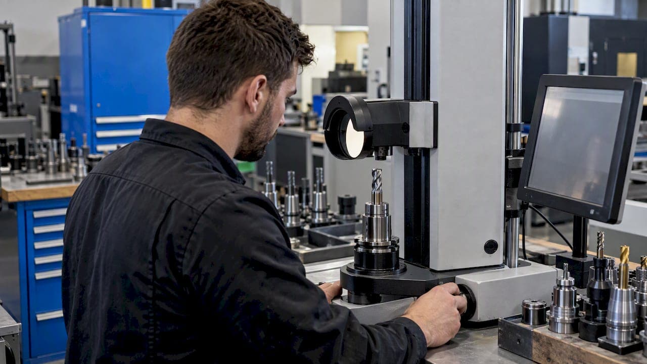
A good tool presetting workflow moves tool measurement off the machine and into a repeatable routine: assemble the tool completely, measure it on a presetter, send the data to the control without retyping it, verify against a master tool, and log what happened. Done in that order, the spindle keeps cutting while the next job's tools are prepared elsewhere.
This guide walks through each stage, the mistakes that quietly ruin offsets, and how to keep the records so the process survives shift changes and staff turnover.
TL;DR
- Preset only a finished assembly. Changing a collet, sleeve or insert afterward invalidates the measurement.
- Never retype offsets if you can avoid it. Manual entry is where "fat finger" errors come from, and barcode, RFID or direct network transfer removes them.
- Verify the presetter with a calibrated master tool at the start of each shift, especially if it sits near machines or coolant.
- Put the base preset in the geometry offset and keep the wear offset for in-process corrections.
- Presetting is as much shop organization as measurement: one tooling location, one numbering scheme, one log.
Table of Contents
- What presetting actually changes on the shop floor
- The workflow at a glance
- Stage 1: Plan from the program, not from memory
- Stage 2: Assemble the tool completely
- Stage 3: Measure length, diameter and runout
- Stage 4: Get the data into the control without retyping
- Stage 5: Verify the presetter, then the first part
- Stage 6: Log tool life and changes
- Organizing the crib around the presetter
- Our perspective: presetting fails on records, not on measurement
- Where Availzye Machinist Pro fits
- A starter routine you can adopt this week
- Common mistakes to avoid
- FAQ
- Sources
What presetting actually changes on the shop floor
Tool presetting means measuring a cutting tool, in its holder, outside the machine. The presetter finds where the cutting edge sits relative to the spindle interface, so the control can be given length and diameter values before the tool ever enters the magazine.
The payoff is machine time. A Modern Machine Shop case study from a job shop reported setup falling from 6.4 hours to 1.5 hours, and the same article puts the saving at roughly 1 to 3 minutes of idle machine time per tool measured. That article dates from 2001, and your numbers will differ with part mix and tool counts, but the mechanism has not changed: touching off tools at the machine means the spindle is not making parts.
There is a second benefit that is easy to miss. Practitioners describe presetting as a preventative action that centralizes tooling and ends the "operator roaming" spent hunting for holders, collets and inserts. A presetter on its own does not fix that. The workflow around it does.
The workflow at a glance
| Stage | What happens | What goes wrong if skipped |
|---|---|---|
| 1. Plan | Tool list pulled from the program or setup sheet | Missing tools discovered at the machine |
| 2. Assemble | Holder, collet, tool and insert built and torqued | Preset value no longer matches the tool |
| 3. Measure | Length, diameter and runout recorded | Crashes, undersize or oversize features |
| 4. Transfer | Data goes to the control by scan, tag or network | Typos in offset fields |
| 5. Verify | Master tool check and first-piece confirmation | Silent drift in the presetter |
| 6. Log | Tool life, wear and changes recorded | No traceability, repeat mistakes |
The rest of this article takes these in order.
Stage 1: Plan from the program, not from memory
The workflow starts before anyone touches a holder. Pull the tool list from the program and the setup sheet, and decide which tools are already in the machine, which are in the crib, and which must be built new.
In the Modern Machine Shop case, the operator started a setup by checking a board listing jobs the presetter had already prepared, ticking off the next one and collecting the matching tools. Whatever your version of that board is (a whiteboard, a screen, a printed sheet), the principle is the same: the presetter operator works one job ahead of the machine.
A consistent tool numbering system matters here. If T12 means a different tool in every program, the presetter record cannot be trusted by whoever loads the magazine. Settle numbering within your controller's limits first, then build the routine on top of it. A one-page CNC setup sheet that lists tool number, holder, stick-out and offset slot gives the presetter operator exactly what they need.
Stage 2: Assemble the tool completely
This is the rule that causes the most quiet trouble: a preset is only valid for the assembly that was measured. If someone changes a collet, adds a reducing sleeve, or adjusts an insert afterward, the measurement no longer applies.
Practical habits that help:
- Build the whole assembly at the bench: clean taper, correct collet, tool seated to the planned stick-out, insert screws or nut torqued to spec.
- Measure only after the last adjustment. If you must adjust, re-measure.
- Keep holders for presetting in the same interface family as the machine. Practitioners point out that the presetter's gauge line has to match the machine spindle interface exactly, because any misalignment there carries straight into the part.
- Clean the taper and the presetter spindle every time. Chips and film on a taper look like length error.
Stage 3: Measure length, diameter and runout
On the presetter, load the assembly, locate the cutting edge, and record length and diameter. Most shops also check runout at this point. One machinist on a public forum noted that the ability to check runout quickly is a big benefit, and it makes sense: a tool that runs out at the bench will run out in the spindle. Reject it there rather than discovering it as a poor finish.
What you record should match what the control expects:
- Tool length from the gauge line to the tip, in the units your control uses.
- Diameter or radius, depending on how the program and cutter compensation are set up. If you use controller compensation, see our notes on CRC versus CAM offsets so the diameter you preset is the one the program assumes.
- Actual stick-out and assembly ID, so the record ties to a physical tool.
Geometry versus wear
Put the base preset in the geometry offset. Reserve the wear offset for corrections made during the process, such as a few tenths to bring a bore in. Keeping the two separate preserves traceability for quality audits: anyone can see what the tool measured on day one and how far it has been nudged since.
Stage 4: Get the data into the control without retyping
This is where many presetting programs lose their value. A perfect measurement typed into the wrong offset register is worse than no measurement. Practitioners list "fat finger" entry errors among the main risks that automated transfer removes.
Transfer methods run from least to most robust:
- Manual keying from a printed label or screen. Cheapest, and the most error-prone.
- Barcode or QR scanning of a label that carries the offset values.
- RFID chips in the holder, which carry the data with the tool.
- Direct network or DNC transfer from the presetter to the control.
If you are starting out and your machines do not support the higher-end options, do not give up. Many shops begin with a printed tool label that lists tool number, length and diameter in large type, and a second person who reads values back while the operator keys them. It is slower than automation, but it catches the transposed digit.
Whichever method you use, the rule is that the value travels with the tool or the job, not in someone's head.
Stage 5: Verify the presetter, then the first part
A presetter is a measuring instrument, and instruments drift. Expert guidance cited in the research recommends measuring a calibrated master tool at the start of each shift, with results within about ±0.0005" for critical aerospace or medical work. A published example of a troubleshooting checklist uses the same logic: measure a master tool of known length and confirm the reading falls within ±0.0005", then review the presetter's logs for profile changes or calibration resets.
Location matters. Vibration is a leading cause of drift in optical presetters, and installations near CNC machines, chip conveyors or high-pressure coolant can degrade accuracy over time. The same source argues that master-tool checks stay necessary even when no software warning appears.
As for standards, a 2025 paper in MM Science Journal notes that no specific international standard governs traceability of tool presetting systems, so shops typically lean on measurement-uncertainty guidance such as ISO 15530-3. If you work to an aerospace or medical customer's quality requirements, ask that customer's quality contact what verification evidence they expect, and write your master-tool routine to satisfy it.
First-piece confirmation
Presetting reduces the need to touch off at the machine, not the need to inspect. On the first part of a new setup, confirm the critical dimensions, and record any wear offset applied. If the first part is consistently off by the same amount in the same direction for a given tool, suspect the preset or the assembly before you suspect the program.

Stage 6: Log tool life and changes
The last stage is the one that makes the first five improve over time. Record, per tool assembly:
- Preset date, operator and values
- Jobs run and parts or minutes cut
- Wear offsets applied and why
- Reason for retirement (wear, breakage, chipped insert)
Some modern presetting systems add camera-based inspection, and one manufacturer describes AI-supported flank wear measurement that can flag worn tools before they affect part quality. You do not need that to benefit from the idea. A simple log with a retirement threshold gives you the same decision, just with a human making it.
Organizing the crib around the presetter
The research is blunt on this point: buying a presetter is not enough. The shop also needs to centralize tooling in one location near the presetter. If holders live in drawers at each machine, the presetter operator spends the saved time walking.
A workable layout:
- One crib or cart zone with holders sorted by interface and size
- Preset-ready tools in labeled trays by job or machine
- A return location for used tools, with a clear "inspect or retire" bin
- Minimum stock levels for consumables such as inserts and collets
Our guide to a tool crib layout built on minimal records covers how to phase in tracking without drowning the crew in paperwork. And if you are measuring the overall effect on changeovers, the approach in reducing setup time shows how to baseline before you change anything.
Our perspective: presetting fails on records, not on measurement
We build shop tools for machinists, and the pattern we hear again and again is that the presetter itself is rarely the weak link. The weak link is what surrounds it: a tool list in one spreadsheet, offsets on a sticky note, tool life in someone's memory, and a crib nobody can count.
Our view is that the workflow only holds when three things sit together. The calculation side tells you what the tool should do: speeds and feeds, deflection at the stick-out you assembled, power and torque at the engagement you plan. The inventory side tells you what exists: which holders are built, which inserts are low, which tools are near end of life. And the job side ties both to a work order, so the next shift sees what the last shift learned.
That is why Availzye Machinist Pro puts the calculators, the Tool Crib with low-stock alerts and tool life logging, the Job Tracker and shift notes in one cloud application. Stick-out is a good example: it appears on the presetting record and it also drives deflection. If those live in different places, nobody checks one against the other.
We do not replace a presetter, and we do not claim to. What we want is for the data around it to be as disciplined as the measurement itself.
— Availzye
Where Availzye Machinist Pro fits
If your presetting routine is mostly sound but the records are scattered, our Tool Crib handles inventory with check-in, check-out, restock and write-off, plus tool life logging and low-stock alerts. Plans are published at $9.99 CAD per month for Individual, $24.99 CAD per month for Small Shop and $49.99 CAD per month for Team, with a 7-day free trial. You can compare them on the Availzye Machinist Pro plans page and try the tools against a real job before committing.
A starter routine you can adopt this week
You do not need new hardware to improve your workflow. Try this on one machine for two weeks:
- Pick one recurring job with at least five tools.
- Write the tool list on a setup sheet with tool number, holder, stick-out and offset slot.
- Assemble and measure every tool at one bench the day before.
- Label each tool with its values in large type, or scan them if you have the capability.
- Read values back when entering them into the control.
- Measure a master tool at the start of the shift and write the reading down.
- Log wear offsets with a reason, every time.
- Compare setup time and first-piece scrap against the previous run.
If the numbers improve, extend the routine to the next job. If they do not, look at the stage where the process stalled; it is usually transfer or assembly, not measurement.
Common mistakes to avoid
- Presetting before the assembly is final. Re-measure after any change.
- Mixing geometry and wear. Overwriting the base preset with corrections erases your audit trail.
- Placing the presetter beside a noisy machine. Vibration and coolant mist degrade accuracy, so give it a stable spot.
- Skipping the master-tool check because nothing looks wrong. Drift does not announce itself.
- Treating presetting as one person's job. If only one employee understands the process, it fails when they are off.
FAQ
How is tool presetting different from touching off at the machine?
Touching off measures each tool in the spindle, so the machine is idle while you do it. Presetting measures the assembled tool offline, so the machine can keep cutting. Research reported savings of about 1 to 3 minutes of idle time per tool measured, and the gain compounds across a long tool list.
How often should I verify a tool presetter?
Guidance in the research is to measure a calibrated master tool at the start of each shift, and weekly or at shift change at minimum when the unit sits near vibration or coolant. Accept a result within about ±0.0005" for critical work, and check your customer's requirements.
Should presetting values go in the geometry or wear offset?
Geometry should hold the base preset. Wear is for corrections made while the part is in process. Keeping them separate lets you see the tool's original measurement during a quality audit.
Do small shops need a presetter to benefit from this workflow?
Not to start. The disciplines of full assembly, labeled values, read-back entry, a master check and a tool log apply with any measuring method. A presetter or automated transfer adds speed and removes keying errors once volume justifies it.
Sources
- Cutting Time, Modern Machine Shop
- A Practical Guide To Presetters, Modern Machine Shop
- CNC Tool Presetting Procedure for Reliable Offsets, Protool Precision Tools
- Fixing Speroni TSP-46 Tool Presetter Measurement Errors, Industrial Monitor Direct
- Impact of high angular resolution on tool geometry assessment, MM Science Journal
- AI-supported flank wear measurement, Heidenhain