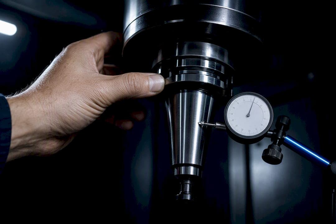
Runout redistributes cutting load unevenly across your flutes, and that imbalance is what quietly wrecks tool life and surface finish. When one tooth takes a heavier bite than the others, it wears faster, generates more heat, and can excite vibration that neither your feeds nor your speeds will fix. The fix starts on the machine, not in a calculator: check total indicated runout (TIR), inspect holder seating and drawbar torque, and only then look at your cutting parameters.
TL;DR:
- Properly controlling runout on small-diameter tools and light finishing passes is critical, as even minimal runout can double chip thickness and cause premature wear.
- Regularly checking total indicated runout with a dial indicator and fixing mechanical issues like spindle bearings can extend tool life by up to 40% and improve surface finish.
- Runout causes uneven forces and chip loads, leading to asymmetrical wear patterns, and often results in higher instability at speeds matching machine or tool harmonic frequencies.
- Radial runout primarily impacts flute-to-flute force balance, while axial runout affects hole depth consistency and surface scalloping, so both should be measured for critical operations.
- Using runout data within integrated measurement and maintenance systems helps develop repeatable processes and prevents unnecessary parameter adjustments.
Table of Contents
- Tool Runout Effects on Chip Thickness, Forces, and Stability
- Runout vs Concentricity: What You're Actually Measuring
- Why the Same Runout Number Hits Some Tools Harder
- A Quick Runout Verification Sequence You Can Run Today
- How Tool Runout Shapes Wear Patterns and Life Predictions
- What Runout Does to Cutting Forces and Torque Readings
- Radial Runout vs Axial Runout: Two Different Failure Modes
- Treat Runout as a Systems Problem, Not a One-Time Fix
- Turning Runout Data Into a Repeatable Shop Workflow
- Sources
- FAQ
Tool Runout Effects on Chip Thickness, Forces, and Stability
When a tool has runout, its flutes no longer trace the same circle. One tooth ends up cutting a thicker chip than its neighbors, while the opposite tooth may barely touch the material. That imbalance creates unequal cutting forces flute to flute, and a 2006 milling study found this produces periodically varying chip loads that can cause premature cutting-edge failure and altered surface topography. The overloaded tooth chips or wears prematurely while the underloaded one coasts, so your effective tool life gets set by the worst flute, not the average.
There's a second, less obvious problem: frequency. Runout injects energy at the spindle's rotational speed and its harmonics. If that frequency content lands near a structural natural frequency in your machine, tool, or workpiece setup, you get new instability at speeds that should otherwise be perfectly quiet. That same 2006 study connects runout harmonics directly to shifts in the stability lobes that define your safe chatter-free RPM pockets.
Surface roughness gets stranger under runout too. Research on runout's effect on process forces and tool wear shows Ra doesn't always climb in a straight line as runout increases. Sometimes a moderate runout value produces a worse finish than a slightly larger one, because the interaction between chip thickness variation and tool deflection isn't linear. That's why modeling and direct measurement both matter. You can't eyeball your way to a runout diagnosis; you need a number, and you need to know what that number means for the specific tool and cut you're running.
Runout vs Concentricity: What You're Actually Measuring
Runout and concentricity get used interchangeably on the shop floor, but they're not the same GD&T callout. Runout measures radial deviation of a surface as it rotates around an axis, checked directly with a dial indicator while the part or tool spins. Concentricity is a location tolerance comparing the median points of cross sections to a datum axis, and it requires far more elaborate measurement to verify correctly. Total runout adds an axial component, controlling both radial and axial deviation across an entire surface at once. Shops substitute simple runout checks for concentricity constantly, and industry guidance on the distinction confirms that's a practical, defensible shortcut for most tool-holding inspections.
For a shop-ready check, mount the tool or a test arbor and indicate at three points: about 25 millimeters from the flange, at the midpoint, and about 25 millimeters from the free end. Rotate by hand rather than jogging the spindle, since a hand rotation protects both your indicator and your fingers. A 0.0001 inch indicator resolution is preferred, with 0.0005 inch as an absolute floor for readings that actually mean something. If your readings grow substantially between the near and far points, you're likely looking at angular misalignment rather than a simple offset, which usually points to the taper or the holder rather than the tool itself.
Why the Same Runout Number Hits Some Tools Harder
A 0.001 inch runout reading means almost nothing on its own. It has to be measured against your feed per tooth. Run a 0.062 inch micro end mill at 0.0005 inches per tooth, and that same 0.001 inch runout is now double your intended chip thickness.
That's exactly the mechanism a 2017 peer-reviewed micro-milling study documented: runout causes unequal chip thickness and unequal cutting forces between teeth, and it can get bad enough that only one flute actually cuts while the rest ride along doing nothing useful. One flute absorbing the entire load wears out fast and destabilizes the cut in the process.
The practical rule: prioritize runout control hardest on small-diameter tools, light finishing passes, and anything carrying a tight Ra callout. Roughing a two inch diameter cutter at 0.008 inches per tooth can tolerate runout that would be catastrophic on a light finish pass. Before you commit to a feed per tooth on a small tool, run the numbers through a chip load calculator and compare that figure honestly against what your indicator is telling you.
A Quick Runout Verification Sequence You Can Run Today
-
Clean the taper, holder, and tool shank, then seat the test arbor or tool fully before measuring anything.
-
Mount your indicator and check at roughly 25 millimeters from the flange, at the midpoint, and roughly 25 millimeters from the free end.
-
Rotate the spindle by hand, never with the machine jog, and record the maximum and minimum indicator readings at each point.
-
Subtract minimum from maximum to get your TIR, then compare that figure against your intended feed per tooth for the job at hand.
A quarter-inch finishing endmill running light chip loads wants TIR well under a thousandth. A two-inch roughing cutter has far more room to breathe. Once you've made a mechanical fix, re-cut a test part and check the surface finish before you trust the parameters going back into production.
How Tool Runout Shapes Wear Patterns and Life Predictions
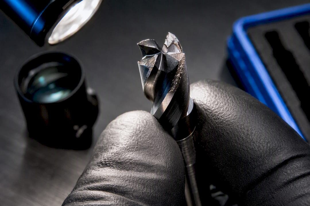
Runout doesn't just shorten tool life, it changes the shape of the wear itself. Instead of even flank wear distributed across every cutting edge, you get one flute carrying visibly heavier wear, chipping, or built-up edge while its neighbors look almost new. That asymmetry throws off any tool life prediction built on the assumption of balanced wear, because the model is estimating an average condition that never actually existed in the cut.
This matters most for anyone tracking tool life against a fixed part count or cycle time. A tool that's supposed to last 400 parts based on published wear data might fail at 250 because one flute did most of the work the whole run. The 1.2379 steel study found that correcting runout not only extended average tool life but reduced operating stress on the tool by roughly 15%, which is the kind of number that shows up directly in your consumable spend even if nobody's tracking wear patterns visually.
The practical implication: if a tool is dying faster than expected, don't assume it's a bad batch or the wrong coating before you check runout. Pull the tool and look at the wear pattern under a light. Uneven wear across the flutes, concentrated on one or two edges, is close to a signature for a runout problem rather than a material or parameter issue. Logging that wear pattern alongside your tool life data over time turns a vague hunch into a documented trend you can act on before you burn through another batch of otherwise-good tooling.
What Runout Does to Cutting Forces and Torque Readings
Cutting force and torque measurements get distorted the moment runout enters the picture, because the sensor is reading the sum of unequal contributions from each flute rather than one consistent, repeating signal. A tool with real runout produces a force signature with a strong component at once-per-revolution frequency, layered on top of the tooth-passing frequency you'd expect from a perfectly concentric cutter. That once-per-rev spike is often the clearest diagnostic signature available if you have force or vibration monitoring on the spindle.
Average torque readings can look deceptively normal even when runout is significant, because the overloaded flute and underloaded flute partially cancel out in an averaged reading. Peak force per revolution tells a very different story, and it's the peak, not the average, that correlates with edge chipping and premature failure. This is part of why the 2019 modeling work on runout errors emphasizes simulation alongside direct measurement. A force trace that looks fine on average can be hiding a peak load spike that's quietly destroying one edge of your tool.
If you're using cutting force or spindle load data to tune your process, treat runout as a variable you need to rule out first. A load spike that seems tied to material inconsistency or tool wear might just be an uncorrected runout problem restating itself every revolution. Fixing the mechanical cause before trusting force-based process monitoring saves you from chasing a phantom material problem that was never there.
Radial Runout vs Axial Runout: Two Different Failure Modes
Radial runout is the one most machinists think of first: the tool tip wobbles side to side relative to the spindle axis as it rotates, and it's what an indicator on the tool's outer diameter measures directly. It drives the unequal chip thickness and force imbalance covered earlier, and it's the dominant cause of flute-to-flute wear differences on end mills and drills doing side-milling work.
Axial runout is different. It's end-to-end wobble along the spindle axis, and it shows up most clearly on face mills, insert cutters with multiple axial cutting edges, and drills where the tip position matters for hole depth consistency. Axial runout on a face mill means some inserts cut slightly deeper than others on every pass, leaving a stepped or scalloped surface even when radial runout is well controlled. On a drill, axial runout translates into inconsistent hole depth and can concentrate wear at the tip rather than along the cutting lips.
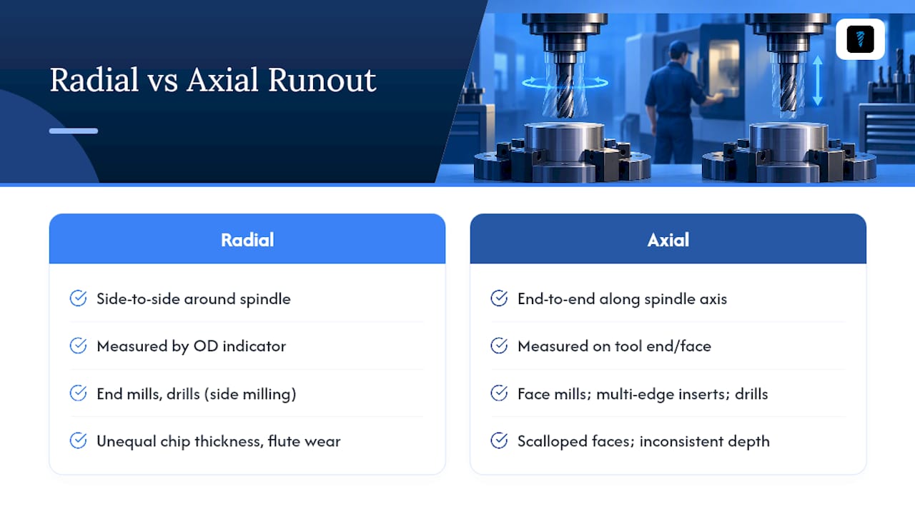
Total runout, as the GD&T definition specifies, controls both simultaneously across an entire surface, and that's the tolerance you want if a part genuinely needs both radial and axial deviation held tight. In practice, most shop-floor runout checks focus on radial runout because it's faster to measure and it drives the majority of tool-life problems in milling and drilling. But if you're running face mills or seeing an oddly consistent depth error on drilled holes, check axial runout specifically rather than assuming a single radial measurement has told you the whole story.
Treat Runout as a Systems Problem, Not a One-Time Fix
The habit that separates shops with predictable tool life from shops constantly firefighting is simple: they check runout on a schedule, not just when something breaks. Runout control couples three things that usually live in separate silos: maintenance records, measurement data, and process monitoring. Log every runout check next to your maintenance actions and your tool life numbers, and patterns emerge that a single measurement never reveals. Pair that data with a feeds and speeds calculator and chatter analysis, and you stop guessing whether a bad part was a tool problem, a parameter problem, or a mechanical one.
— Availzye
Turning Runout Data Into a Repeatable Shop Workflow
Measuring runout is only half the job. The other half is doing something useful with that number before the next job hits the machine, and that's where a lot of shops lose the thread between a good indicator reading and an actual process fix. Some software platforms close that gap by keeping your measurement data, calculators, and maintenance history in one cloud-synced application instead of scattered across paper logs, spreadsheets, and multiple apps.

Once you've got a TIR reading, feed it straight into the Feeds & Speeds and Tool Deflection calculators to see how that runout interacts with your intended chip load, or run a Chatter Prediction check if you suspect the harmonics are drifting into an unstable zone. The Maintenance Tracker logs spindle service and holder swaps alongside Tool Life records in the Tool Crib, so when tool life jumps after a repair, you have the data to prove it rather than a hunch. Individual access starts at $9.99 CAD per month, with Small Shop and Team tiers built for multi-machine operations. A 7-day free trial gets you into the full platform, no drawbar required.
Sources
Work through the mechanical stack before you touch a single cutting parameter. Runout almost always traces back to one of a handful of culprits, and they're worth checking in order:
- The effect of milling cutter teeth runout on surface topography, surface location error, and stability
- Tool run-out measurement in micro milling (MDPI, 2017)
- Concentricity and runout measurement guidance (GDT basics)
If runout persists after all of that, suspect the spindle bearings or a damaged taper, and budget for service. A 2024 experimental study on machining 1.2379 tool steel found that after spindle maintenance addressed runout, tool life increased by roughly 40%, alongside measurable gains in surface roughness and dimensional accuracy. A separate 2024 drilling study reached a similar conclusion: eliminating runout through spindle maintenance improved hole roughness, accuracy, and drill life at the depths tested.
Pro Tip: Replacing inserts or swapping to a "better" tool coating won't fix runout caused by a worn spindle bearing. You're treating a symptom while the mechanical cause keeps grinding away at whatever tool you put in next.
Resist the urge to compensate by simply backing off feed and speed. Redistributing an already unequal load by slowing everything down can shift excitation into a chatter-prone frequency instead of solving the underlying problem.
FAQ
What Is Considered an Acceptable Amount of Tool Runout?
There's no universal number, since acceptable runout depends on tool diameter and intended feed per tooth. A finishing pass on a small-diameter tool needs runout held far tighter than a roughing operation on a large cutter, so compare your TIR reading against your actual chip load rather than a fixed target.
How Do I Measure Spindle Runout on My Machine?
Mount a test arbor, clean and seat it fully, then indicate at roughly 25 millimeters from the flange, at the midpoint, and roughly 25 millimeters from the free end. Rotate by hand and record the difference between maximum and minimum readings using an indicator resolution of 0.0001 inch preferred, 0.0005 inch minimum.
Can I Just Adjust Feeds and Speeds Instead of Fixing Runout?
Changing parameters doesn't remove the mechanical imbalance causing the runout, and it can shift vibration into a worse frequency range. Fix the mechanical cause, spindle, holder, or drawbar, then revalidate your cutting parameters once TIR is back in range.
What's the Difference Between Runout and Concentricity?
Runout measures radial deviation of a rotating surface, checked with a simple dial indicator, while concentricity is a location tolerance comparing cross-section median points to a datum axis, which requires far more elaborate measurement. Most shops substitute runout checks for concentricity in practice because it's faster and generally good enough.
Does Fixing Runout Actually Improve Tool Life?
Yes. A 2024 study on 1.2379 tool steel found spindle maintenance that corrected runout produced roughly a 40% increase in average tool life, along with measurable improvements in surface roughness and dimensional accuracy.