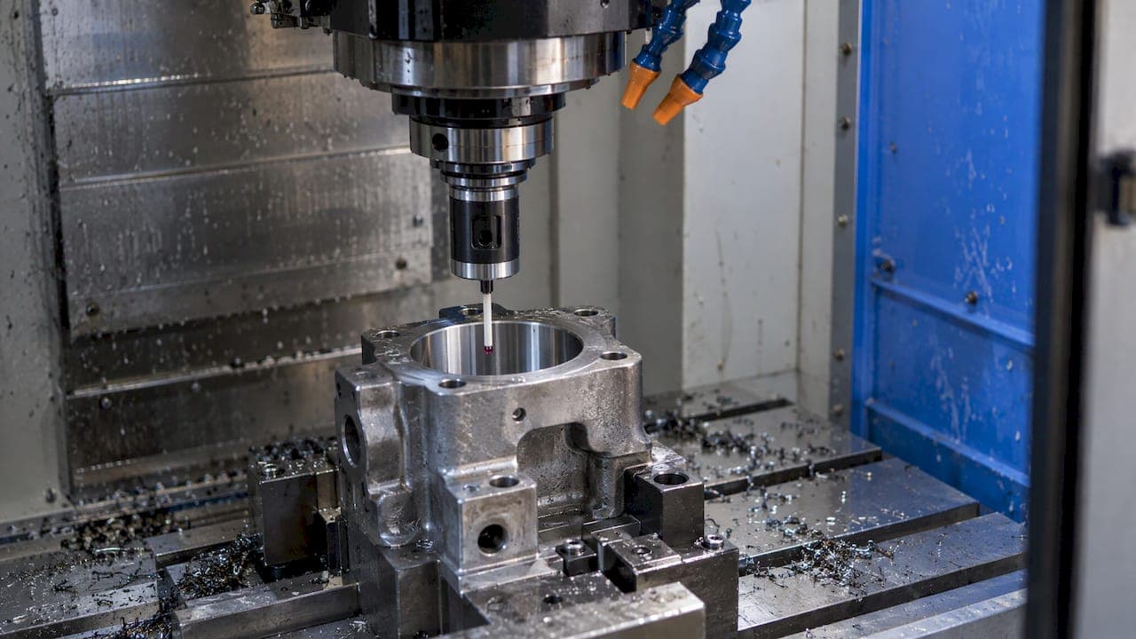
In-process probing means measuring a workpiece on the machine, after cutting has started and before the part leaves the fixture, then using the result to adjust the process. A touch probe in the spindle checks a feature, the control compares it to the target, and an offset gets corrected before the final cut. NIST defines on-machine in-process measurement in just those terms: measurement after cutting starts and before the part is unclamped, either continuous during cutting or intermittent during a pause.
This guide covers what the probe does, where it pays off, how to build a routine you can trust, what limits its accuracy, and when a part still needs a real inspection.
TL;DR
- In-process probing measures a feature mid-job, while the part is still fixtured, and feeds the result back into work or tool offsets.
- It pays off most for setup, tool wear and thermal drift, and for catching misloaded or oversize parts before they turn into scrap.
- A reliable routine needs a clean part, a calibrated probe, a defined decision (what is measured, what gets adjusted) and a verified final cut.
- Probing is a supplement to inspection, not a replacement for a CMM, especially for tight tolerances and form controls like flatness or roundness.
- Keep probe results, offsets and job notes in one place so the next shift can see what the machine corrected and why.
Table of Contents
- What in-process probing actually is
- Why shops probe mid-process
- The cut, probe, adjust loop
- Setting up a probing routine you can trust
- What limits probing accuracy
- When in-process probing is enough, and when to inspect
- What does a probing system cost?
- Our perspective
- Put the numbers and records in one place
- A practical rollout plan
- FAQ
- Sources
What in-process probing actually is
A CNC probe is a sensor that mounts in the machine. The most common type is a touch-trigger spindle probe. Renishaw explains that it signals the controller when the stylus touches the part, and the controller then captures the machine position from encoder feedback. That captured position is the measurement.
In practice the probe usually lives in the tool magazine. Cutting Tool Engineering notes it gets loaded like any other tool. The typical trigger mechanism is a stylus that moves off a kinematic seat, breaking electrical continuity and firing the signal.

Pre-process, in-process and post-process
The same probe does different jobs depending on when you use it. NIST's framework separates pre-process, in-process, intermittent and post-process roles. Modern Machine Shop describes the same three timing points in shop terms:
| When | Typical job | What it answers |
|---|---|---|
| Before cutting | Setup, finding part zero, detecting a misloaded part, adapting to raw stock | Is the part where the program thinks it is? |
| During cutting | Checkpoints, offset updates, diagnosis | Is the process still making what we intend? |
| After cutting | Rough screening | Are these parts likely good or bad? |
Only the middle row is truly in-process probing. The other two matter because they set up and confirm it.
Why shops probe mid-process
Machining has variation built in. Renishaw's process-control model treats probing as feedback against it: the predictable setup variation is attacked first, then the inherent variation such as tool wear and temperature change that shows up as the run goes on.
The practical benefits break down like this:
- Setup time. Finding part zero and checking stock position by probe replaces manual indicating.
- Fewer keying errors. NIST says automated on-machine measurement can reduce manual intervention, keying errors, rework, concessions and scrap, and improve repeatability and consistency.
- Wear and drift compensation. Probe a finished feature, see it creeping toward a limit, and update the tool offset before it crosses.
- Scrap prevention. Renishaw points out that probing can help correct an oversize feature before scrap is produced, which a post-process check alone cannot do.
- Go/no-go decisions. CTE reports that on-machine probing supports go/no-go checks, workpiece orientation and in-machine tolerance decisions while correction is still practical.
There is a cost: measuring adds time to the cycle. Okuma's white paper says properly implemented in-process gaging still saves time and resources overall by cutting scrap and operator error. The art is probing only where a measurement changes a decision.
The cut, probe, adjust loop
The core pattern is what NIST calls adaptive machining: cut, probe, adjust offsets for deflection, wear or other factors, then make the final cut. Here is a worked example on a bore.
- Rough and semi-finish the bore, leaving 0.010 in. of stock on the diameter.
- Probe the bore at two or more points and calculate the actual diameter.
- Subtract the measured diameter from the target. If the bore reads 0.0040 in. under size on the finish pass, the remaining stock is 0.0040 in. larger than planned.
- Update the finishing tool's diameter offset by the amount the process needs, within limits you set in the macro.
- Make the finish pass, then probe again and confirm the result.
That last probe matters. The adjustment is a hypothesis until the final measurement confirms it.
Why cutter deflection belongs in the picture
A good share of what the probe finds in step 2 is deflection: the tool pushed away from the wall during the semi-finish pass. If you can estimate that before cutting, your first-pass offsets start closer to correct and the probe is correcting small residuals rather than large errors. Our Tool Deflection calculator is built for that estimate, and Feeds & Speeds helps you choose parameters that keep radial force reasonable in the first place.
Setting up a probing routine you can trust
NIST's guidance on setup comes down to a short list. We have turned it into a shop checklist.
1. Define the decision
Decide which feature you are measuring and what you will do with the result. "Probe the bore" is not a routine. "Probe the bore after semi-finish, and adjust offset T12 by the difference, up to 0.003 in., otherwise stop and alert the operator" is one. Add limits so a bad reading cannot drive an offset somewhere ridiculous.
2. Make the probing path clean and reachable
Okuma warns that chips, coolant, approach angle, probe geometry and access all affect a measurement, and recommends measuring when the part is clean. Add an air blast or coolant wash before the probe cycle, and confirm the stylus can reach the feature without collision.
3. Establish probe and work coordinates
The controller needs to know the probe's length and the work offset it is measuring against. NIST notes that measurement code in the control builder's software, or in separate integrated software, directs the spindle-probe moves, and that different probe sizes may require manual or rack-based probe changes. If you are building out this software side, an industrial automation setup process walkthrough can help you think through the order of hardware, tool changes and code.
4. Calibrate against a known reference
Calibrate against a fixed datum sphere or other reference artifact. Okuma describes the datum sphere as a fixed mastering point used to calibrate the probe before it measures the part, and says tighter tolerances require recalibration for tighter readings. Recalibrate after a stylus change, a crash, or a significant temperature swing.

5. Verify the final cut
Prove the loop on a few parts, with the finished features checked independently, before you trust it unattended. Then log what you did.
What limits probing accuracy
The probe measures with the machine's own axes, so the machine's quality sets the ceiling. Modern Machine Shop says machine accuracy, repeatability and thermal behavior all affect the quality and hour-to-hour consistency of probed measurements.
Thermal behavior
A cold machine and a warm one do not measure alike. A consistent warm-up routine removes a good part of that variable. We cover one in our spindle warm-up guide, with copyable G-code and verification steps.
Probe lobing
CTE identifies probe lobing as a directional error: the force needed to overcome the probe's spring mechanism differs by approach direction. It reports that high trigger forces and long styli can increase lobing error by 0.001 in. or more. Keep styli as short and stiff as the feature allows, and calibrate at the speed and direction you actually measure.
Part and process conditions
Chips, coolant film and a part still warm from cutting all show up as measurement error. So does a tool that is already deflecting when you pause. Measure in a consistent state, and probe at the same point in the cycle every time.
When in-process probing is enough, and when to inspect
Use probing for setup, process checkpoints, feature size or position, adaptive correction and screening while the part is still fixtured. Use a dedicated inspection step for final acceptance. Modern Machine Shop's guide is direct that in-machine probing supplements inspection and does not replace a coordinate-measuring machine, because the machine is measuring itself. It adds that tight or barely out-of-tolerance conditions, and geometric controls such as roundness, flatness or squareness, are poorly handled by most in-machine probes.
| Situation | Probe in process | Inspect after |
|---|---|---|
| Finding part zero and checking stock | Yes | No |
| Compensating tool wear between parts | Yes | Sample check |
| Size on a loose or moderate tolerance | Yes | Periodic sample |
| Critical bore at the edge of tolerance | Adjust with probe | Yes, final acceptance |
| Flatness, roundness, squareness callouts | Rough screen only | Yes |
If you want to think about how measurement reliability and the coordinate-measuring role fit together, a probe diameter guide for technicians covers related ground on probe size and measurement consistency.
What does a probing system cost?
Prices swing widely, so we will not quote a single number. The main drivers are the probe type (a spindle touch probe versus a tool-setting probe, or both), the signal transmission method between probe and receiver, the machine control it must work with, and whether you buy software cycles or write your own macros. Installation and training add to the hardware figure. Get quotes from your machine builder and a probe supplier for your exact control and machine model, and compare them against the scrap, rework and setup time your shop actually loses today.
Our perspective
Probing is a measurement activity, and every measurement needs somewhere to live. The probe tells the control what happened to one feature on one part. It does not tell the next shift why an offset moved, or which tool was nearly worn out, or which job was running when the machine warmed up.
We built Availzye Machinist Pro around that gap. Our platform combines machining calculators, including Feeds & Speeds, Tool Deflection and Chatter Prediction, with shop management: a Job Tracker, Tool Crib with tool life logging, a Maintenance Tracker and shift notes. Our view is that the physics you calculate before the cut and the records you keep after it belong in one cloud-synced application rather than spread across spreadsheets, paper logs and separate apps.
A shop that probes well starts the cut with better numbers and ends the shift with better notes. That is the combination we design for.
Availzye
Put the numbers and records in one place
If you run probing cycles, the work does not end at the probe. You still need sensible starting parameters, a view of how much the tool will deflect, and a log of tool life and offsets. Availzye Machinist Pro puts the calculators and shop tracking in one cloud application, with a 7-day free trial. Plans are Individual at $9.99 CAD per month, Small Shop at $24.99 CAD per month, and Team at $49.99 CAD per month. See the details on the Availzye Machinist Pro plans page.
If your probe cycles are G-code macros, run them through the same discipline as any program. Our guides on G-code troubleshooting and verifying AI-generated G-code apply directly to probing macros before they touch the spindle.
A practical rollout plan
Start small. A shop does not need adaptive machining on every job.
- Week one: Use the probe only for setup: part zero and misload detection. This pays back quickly and builds familiarity with calibration.
- Week two: Add a post-cut check on one critical feature of one repeat job. Log the readings.
- Week three: Once the readings show a pattern, such as steady drift as a tool wears, add an offset update with firm limits.
- Ongoing: Review logs, recalibrate on a schedule, and fold the probe into your regular maintenance routine. Our CNC maintenance checklist maps tasks to service intervals.
FAQ
What does probing mean in CNC machining?
Probing means using a machine-mounted sensor, usually a touch-trigger probe in the spindle, to touch a workpiece and send the contact position to the controller. The controller uses that position to find part zero, check a dimension or correct an offset.
What is the difference between in-process probing and post-process inspection?
In-process probing happens while the part is still in the fixture, so a correction can still change the outcome. Post-process inspection checks the finished part against specification, ideally on a CMM for final acceptance, and cannot fix an oversize feature.
Can in-process probing replace a CMM?
No. The machine is measuring itself, so its accuracy, repeatability and thermal behavior limit the result. Use probing to screen and correct, and use dedicated inspection for tight tolerances and form controls like flatness or roundness.
How much does a CNC probe cost?
It depends on the probe type, the signal transmission, your machine control and whether you add software cycles and installation. Ask your machine builder and a probe supplier for quotes specific to your machine model.
Sources
- On-Machine Measurement Use Cases and Information (NIST)
- Probing systems for CNC machine tools (Renishaw)
- When do I probe? (Renishaw)
- Machine tool probes for workpiece set-up and inspection (Renishaw)
- The basics of on-machine probing (Cutting Tool Engineering)
- What Should Machinists Know About In-Machine Probing? (Modern Machine Shop)
- Maximize the Benefits of Today's In-Process Gaging Technologies (Okuma)
- Industrial automation setup process: a step-by-step guide
- Industrial Camera Probe Diameter Guide for Technicians