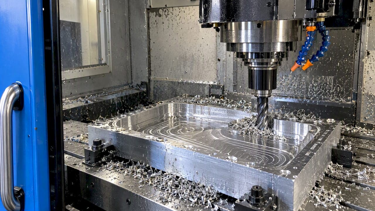
Toolpath optimization means controlling how the cutter enters the material, how much of it is engaged at any moment, and how it leaves, so the part comes off faster, with a better finish and less tool wear. The strategies that matter most are smooth entry and exit, constant engagement (adaptive or dynamic roughing), sensible stepover and rest-stock choices, the right cut direction, and a measured before-and-after check. This guide walks through each one and shows how to verify that a change helped.
TL;DR
- Most gains come from keeping cutter engagement constant: adaptive and dynamic roughing beat plain pocket zig-zag in published tests.
- Roll or arc into the cut and avoid exiting with a thick chip. Entry and exit are where carbide chips.
- Pick stepover, axial depth and feed together, from the tool maker's chip-load data, not one at a time.
- Climb milling is the usual default for finishing, but conventional has real uses on weak setups.
- Change one variable per trial, then compare cycle time, tool life and part quality against a baseline.
Table of Contents
- What toolpath optimization actually changes
- Start with the right toolpath family
- Roughing strategies: keep the load constant
- Entry and exit: where tools are actually lost
- Coordinate stepover, depth and feed
- Choose cut direction on purpose
- Finishing: path pattern and surface
- Check the G-code, not just the preview
- Perspective: optimize the system, not just the path
- Measure whether the change worked
- Put it into a shop workflow with Availzye Machinist Pro
- FAQ
- Sources
What toolpath optimization actually changes
A toolpath is the route the cutter follows, and it decides more than travel distance. It sets the radial and axial engagement, the chip thickness at each point, how heat and chips are carried away, and how often the tool slams into or out of material. Optimizing it can shorten cycle time, extend tool life, and improve surface finish, but these goals can pull against each other. A review of AI-assisted toolpath generation notes that the approach has significant potential but limited use so far, partly because of computing demands, and that it must balance objectives such as cost and sustainability.
That balance is the real job. A path that is fastest on the clock can wreck a tool, and a path that protects the tool can leave money on the table. The strategies below are ordered the way you meet them on the floor: pick the toolpath family, manage entry and exit, control engagement, set parameters, choose a cut direction, finish, then measure.
Start with the right toolpath family
Most milling toolpaths fall into two groups. 2D paths hold a constant Z level at a time and cover drilling, contouring and pocketing of flat or shallow features. 3D paths move X, Y and Z together, which is what you need for molds, dies and organic surfaces. Within 2D work you will use facing to establish flat faces, contouring for walls, pocketing, slot milling, chamfer milling and radius milling.
The choice is not only about geometry. NIST observes that in CNC process planning, the intelligence rests primarily with the process designer, who has to combine knowledge of the machine's capabilities with an understanding of machining mechanics. CAM suggests, you decide. In practice that means asking four questions before you accept a default strategy:
- How rigid is the setup, and how much spindle power and torque does the machine have at the RPM you need?
- How long is the tool stickout relative to its diameter?
- Is the material gummy, abrasive, or work-hardening?
- Is the part thin-walled or likely to move when material is removed?
The last three questions are where tool deflection checks earn their keep. If a long, small cutter will deflect under the radial load your strategy implies, no path trick fixes it. Shorten the tool or lighten the cut first.
Roughing strategies: keep the load constant
Traditional pocket roughing steps over at a fixed distance and creates big load spikes in corners and when the cutter is buried in a slot. Adaptive and dynamic strategies address that by holding engagement nearly constant. DATRON describes dynamic paths as using full axial depth with a very light radial cut to maintain chip load, and reports longer tool and spindle life, better finish and higher efficiency.
Independent research points the same way. A 2023 study on milling nickel-based alloys found that adaptive toolpaths produced the smallest tool loads, less wear and better surface roughness than circular or swinging trochoidal strategies, and concluded that a constant contact angle is the route to lower wear and load. Another line of work, a 2022 Springer study, suggests that reshaping trochoidal paths with B-spline curves can give higher productivity than traditional cycloidal trajectories by controlling tool load more closely.
The cycle-time numbers are the part that gets a shop owner's attention. Experimental work on 3-axis machining published in 2026 found that a high-speed dynamic roughing strategy cut cycle time by 22.5% versus pocket zig-zag and 57.6% versus standard area roughing. Treat those as results of one test setup, not a promise for your part. Your gain depends on stock shape, machine acceleration and how much air cutting your current program contains.

When dynamic roughing is not the answer
Dynamic paths ask a lot of the machine: constant direction changes at high feed. A control with a slow look-ahead, or a machine with soft axis acceleration, may never reach the programmed feed on small-radius moves, and the time saved on paper disappears. Check the actual cycle on the machine. If you run trochoidal paths, our guide to trochoidal milling parameters covers engagement, feed and speed in more depth.
Entry and exit: where tools are actually lost
Half of all chipped inserts and snapped end mills happen in the first and last millimeter of a cut. Two habits fix most of it.
Do not plunge straight in when you can ramp. Cutting Tool Engineering and DATRON both describe arc or helical entry as preferable to straight plunging because it reduces entry shock. Helical ramps in pockets and arc-in lead-ins on walls are the standard answer.
Respect the exit. Sandvik Coromant states that cutter exit is the most sensitive phase of milling, because thick chips at exit can fracture carbide edges. Their guidance: roll into the cut, position the cutter off-center rather than symmetrically on the centerline, keep it engaged where possible, and roll around corners instead of making a sharp turn.
In practice:
- Add a lead-in arc and a lead-out arc to every finishing contour.
- Replace sharp inside corners in the toolpath with a small radius, so engagement does not spike.
- Where the cutter must leave the material, make it happen with a thin chip, not a thick one.
- Avoid stopping the cutter on a finished wall. A dwell leaves a witness mark.
Coordinate stepover, depth and feed
A toolpath strategy fixes the pattern, but the numbers inside it decide the result. The guidance from tooling makers is simple: use the manufacturer's chip-load and surface-speed specifications, and account for your spindle's RPM limit. Dynamic strategies pair full-depth axial cuts with very light radial cuts, so the cutting edge length is used evenly instead of wearing one spot.
A common documentation reference for pocket stepover is roughly 10% to 40% of tool diameter, adjusted for material, cutter, depth, spindle power, chip evacuation and machine rigidity. On a 1/2 inch end mill that is a stepover of about 0.050 to 0.200 inch. The low end is where adaptive roughing lives. The high end suits a rigid machine in aluminum with good chip clearing.
One trap at light radial engagement: chip thinning. When the radial cut is a small fraction of the diameter, the real chip is thinner than the programmed feed per tooth, so the tool rubs instead of cutting unless you raise the feed. Our walkthrough on radial engagement milling at 10% stepover shows how to calculate the compensated feed and verify it in CAM. For aggressive axial-light approaches, high feed milling is the related strategy.

Leave the right amount for finishing
Roughing typically leaves 0.2 to 0.5 mm (about 0.008 to 0.020 inch) on walls and floors, so the finishing pass cuts cleanly instead of rubbing. If a finishing tool is deflecting or the part is thin, leave more on the walls and add a semi-finish pass. Uneven stock left by a large roughing tool in corners is the usual reason finishing passes chatter; a rest-machining operation with a smaller tool evens it out first.
Choose cut direction on purpose
Climb milling starts each chip thick and ends it at zero, which is why it is generally preferred for CNC finishing when the machine is rigid and backlash is controlled. Seco notes that climb milling helps chips flow behind the cutter, minimizing recuts and improving surface finish. The same source adds that conventional milling can protect brittle, super-hard tools on rough or thin-walled material and handle heavy cuts on less stable machines.
So the default is climb, with exceptions:
| Situation | Usual choice | Why |
|---|---|---|
| Finishing walls on a rigid machine | Climb | Clean surface, chips clear behind cutter |
| Roughing on a worn or backlash-prone machine | Conventional may be safer | Avoids the cutter pulling itself into the work |
| Thin-walled or rough-surfaced stock | Conventional can help | Protects brittle tooling from the initial impact |
| Heavy cut on a less stable machine | Conventional can help | Lower risk of cutter grab |
If you want to go deeper on the trade-offs, see climb vs. conventional milling, which lets radial engagement, cutting speed, feed per tooth and surface slope drive the decision.
Finishing: path pattern and surface
The finishing pattern influences the surface as much as the cutter does. Spiral, zig-zag and contour-parallel paths each leave a different texture on the finished part, and on 3D surfaces the stepover between passes sets the scallop height. Constant-stepover and rest-machining operations keep scallops even, and pencil milling cleans the leftover in tight fillets. Tighten the stepover on steep walls and open it on flat floors rather than using one value everywhere. For a deeper look at the numbers, our article on toolpath optimization for machinists covers tuning scallops after the first round of time savings.
If the drawing calls out a surface roughness, work backward from that target before you pick the stepover, rather than discovering it on the inspection bench.
Check the G-code, not just the preview
CAM simulation shows the path you intended. The controller runs the G-code you posted. NIST points out that a fundamental weakness of standard G-code is reliance on machine-specific post-processors, which makes toolpath data hard to move between CNC systems. The practical lesson: read the posted code for the first run on any new machine or post. Look at rapid moves near the part, feed rates on arcs, and the coolant and spindle lines.
This matters even more when an AI tool helped write the program. Our piece on how to verify AI-generated G-code before it touches the spindle lays out the checks, and our pilot-first guide to AI in machining covers how to introduce such tools without risking scrap.
Perspective: optimize the system, not just the path
We build calculators and shop tools for machinists, and the pattern we see is consistent: toolpath optimization fails less often because of the wrong strategy than because of unverified numbers around it. A dynamic path with a feed rate that ignores chip thinning rubs. A beautiful adaptive pocket with a long, deflecting cutter chatters. A faster program that nobody logs leaves the shop no wiser next month.
So our view is that the path, the parameters and the shop's records should live together. Run the cutting numbers through feeds and speeds, chip thinning, power and torque, and deflection checks before the program goes to the machine. Then log what happened: which tool, how many parts, what the cycle was. Over a few jobs that log becomes your own reference data, which is worth more than any generic recommendation, including ours.
The second point is about restraint. Do not chase the biggest percentage on a one-off part. Put the effort where the part count is high or the tool costs are painful, because that is where a few seconds per part or a longer-lasting cutter pays back.
— Availzye
Measure whether the change worked
An optimization you did not measure is an opinion. Build a simple routine.
- Set a baseline. Record the current cycle time from a real run, not the CAM estimate, plus tool life (parts or minutes per edge) and a quality measure such as surface roughness or a critical dimension.
- Change one thing. Swap the roughing strategy, or the stepover, or the entry move. Not all three.
- Run enough parts to see a trend. One part can hide tool wear. Three to five on a fresh edge show more.
- Compare the same three numbers. Cycle time, tool life, quality.
- Keep or revert, and write it down.
Gains from code-level cleanup can be modest and still worthwhile. In a 2025 CNC project study, optimizing the G-code reduced machining time from 15 minutes 23 seconds to 13 minutes 33 seconds, roughly 12% on that part. On a run of hundreds, that is hours back. Compare that to the larger roughing-strategy differences above, and you can see why the order of attack matters: start with roughing, then entry and exit, then clean up air cutting and rapids.
Cost is the final measure. Faster cycles that eat tools can raise the per-part price, which is why machining cost estimation belongs in the same conversation as cycle time.
Put it into a shop workflow with Availzye Machinist Pro
The calculations behind these strategies are repetitive: feed per tooth after chip thinning, power at a given engagement, deflection at a given stickout. Availzye Machinist Pro puts those calculators, plus G-code analysis and generation, in one cloud-synced app, and the same account holds a Job Tracker, Tool Crib with tool life logging, and shift notes, so the results of each trial stay attached to the job and the tool. Our G-code generator and tool database are good places to start.
Plans are Individual at CAD 9.99 per month, Small Shop at CAD 24.99 per month and Team at CAD 49.99 per month, each with a 7-day free trial. See the plans and start a trial.

If you are weighing whether cloud tools fit a shop floor, five benefits of cloud CNC software is a quick read, and the AI assistant can help you sanity-check parameters. Always confirm against the tool maker's data and your machine's limits.
FAQ
What are the different types of CNC toolpaths?
The basic split is 2D and 3D. 2D toolpaths work at a constant Z level for facing, contouring, pocketing, slotting, chamfering and radius milling. 3D toolpaths move in X, Y and Z together for molds, dies and sculpted surfaces. Within each, roughing, semi-finishing and finishing strategies handle different stages of material removal.
What is the best roughing strategy for reducing cycle time?
It depends on the part, but adaptive or dynamic roughing, which holds engagement constant with full axial depth and light radial cuts, has outperformed pocket zig-zag and standard area roughing in published tests. The machine must be able to hold feed through frequent direction changes, so verify the actual cycle on your equipment before committing a production run.
Is climb or conventional milling better?
Climb milling is usually preferred for finishing because it gives a cleaner surface and clears chips behind the cutter. Conventional can be the safer option on less stable machines, thin-walled or rough material, or with brittle tooling. Let machine rigidity and backlash condition guide you.
How do I know if a toolpath change really helped?
Record a baseline from a real run: cycle time, tool life and a quality measure. Change one variable, run several parts, and compare the same three numbers. CAM estimates alone are not enough, because the machine's acceleration and the tool's wear determine the real outcome.
Is AI replacing CNC programmers?
Not in the work this article covers. Research describes AI toolpath generation as promising but of limited use so far, and NIST notes that process planning intelligence rests mainly with the process designer. AI output still needs a machinist's review before it reaches the spindle.
Sources
- Recent advancements in AI-assisted tool path generation for CNC machining
- What is CNC Toolpath: Definition, Applications and Types
- The State of Integrated CAM/CNC Control Systems (NIST)
- Dynamic Toolpaths to Optimize CNC Machining
- Effects of Machining Parameters and Tool Reconditioning (PMC)
- Optimisation of tool path shape in trochoidal milling (Springer)
- Analyzing different toolpath options on a 3-axis CNC (IOP)
- Extend tool life with dynamic toolpaths (Cutting Tool Engineering)
- Cutter path and chip formation (Sandvik Coromant)
- CNC Toolpaths and Cutting Tools for Beginners
- Pocket Milling: Definition, Methods, and Best Practices
- Climb vs Conventional Milling on a CNC
- Milling process and mechanical loads (Seco)
- Optimization of Toolpath Planning and CNC Machine (MDPI)