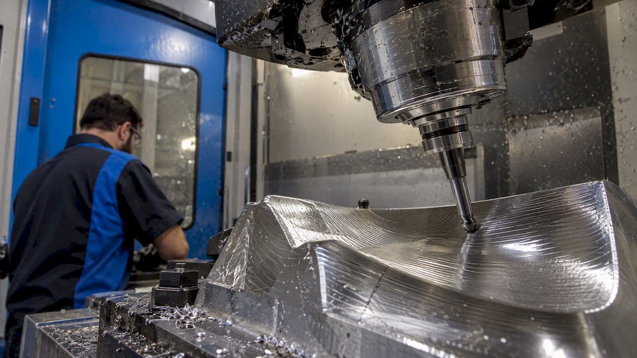
Adaptive toolpaths, two-phase scallop optimization, trochoidal passes in difficult material and ML-assisted strategy selection are the highest-value levers. One two-phase study reported an 11% time cut from parameter search, then 19% more from scallop adaptation. We built Availzye Machinist Pro so you can run the checks and log the results.
TL;DR:
- The adaptive scallop workflow tests tool orientation, tilt, lead angle, and stepover, then selects the fastest variant that keeps remaining material height within tolerance.
- Use adaptive clearing for pockets and long engagements, trochoidal passes for hard materials or narrow slots, and equal scallop finishing on freeform surfaces.
- Machine learning systems predicted freeform strategies with up to 96.4% accuracy; use rankings to shortlist candidates and verify material height and finish on your machine.
- Experimental genetic algorithm optimization reduced noncutting path length by roughly 30% and cycle time by about 7%, so confirm those gains in shop trials.
- Before production, simulate G code for gouges, unintended moves, and holder clearance, then proof cut a coupon and confirm material height and roughness meet specs.
Table of Contents
- 1. Which toolpath strategy fits your part geometry?
- 2. How does the two-phase adaptive scallop method work?
- 3. What can AI and energy-aware optimization add?
- 4. Which advanced techniques and post-processor tweaks help most?
- 5. What should you measure on the shop floor?
- 6. How do you verify toolpaths before they reach production?
- 7. How do tool wear and real-time compensation affect toolpath planning?
- 8. How do you optimize toolpaths for multi-axis machining centers?
- 9. How can you minimize tool changes and setup time?
- 10. How do coolant and chip evacuation shape toolpath design?
- Why disciplined, data-driven optimization belongs in your playbook
- Run these experiments with a toolset built for the shop floor
- FAQ
- Sources
1. Which toolpath strategy fits your part geometry?
No single strategy wins everywhere, so pick two or three candidates and test them on your own part. The common options:
- Zig-zag / one-way: Simple and predictable on open pockets and flat areas. Zig-zag minimizes air time, one-way keeps climbing milling consistent. Both can overload the tool in corners.
- Spiral in/out: Keeps the tool moving without sharp reversals, which suits finishing on rounded features and smooth surfaces.
- Contour / parallel planes: The workhorse for steep walls and thin-wall parts, where constant Z-levels keep deflection predictable.
- Trochoidal milling: Small looping arcs hold engagement steady in slots and hard materials, trading more path length for lower, steadier load.
- Adaptive clearing / constant engagement: Controls the engaged angle so you can run deep axial cuts at high feed without spiking load.
The numbers back this up. An experimental study on freeform surfaces found that Dynamic OptiRough shortened roughing time by 22.5% versus Pocket Zig-Zag and 57.6% versus area roughing. On finishing, equal scallop gave the best roughness in concave regions, while constant scallop balanced differently, so the right choice depends on whether you chase time or surface quality.
Use adaptive clearing for pockets and long tool engagement, trochoidal passes for hard materials and narrow slots, and equal-scallop finishing for freeform surfaces.
2. How does the two-phase adaptive scallop method work?
The method mirrors what the two-phase research validated: search parameters for the shortest time first, then push the stepover as far as your scallop limit allows. A Springer paper describes the same search over tool orientation, angles and stepover for circular-edge tools, followed by an adjusted scallop_OPT that keeps remaining material height (RMH) in tolerance.
- Generate parameter variants: tool orientation, tilt and lead angles, and stepover.
- Run each variant through your CAM and record machining time and maximum RMH.
- Pick the fastest variant that stays within your scallop limit. This was the phase that delivered the 11% reduction.
- If maximum RMH sits below the allowed scallop, increase scallop_OPT in small increments and recalculate.
- If RMH exceeds the limit, reduce scallop_OPT and recalculate.
- Stop when RMH lands within tolerance of the limit. This second phase added the further 19% in the study.
Pro Tip: Automate variant generation if your CAM supports parameter sweeps; if not, script it, and cut a short test coupon so you can check the surface before committing a full part.
Our scallop height guide and spreadsheet covers the RMH math behind the adaptive loop.
3. What can AI and energy-aware optimization add?
Machine learning will not replace your judgment, but it can shrink a long list of strategies down to a shortlist worth testing. Research published in 2026 reported ML systems integrated with CAM that predict the best toolpath strategy for freeform surfaces, weighing energy, machining time, part quality and path smoothness.
Reported accuracy: up to 96.4% for predicting the best strategy on freeform surfaces. Treat that as a high-quality shortlist, not a guarantee for your machine.
Energy modeling adds a second angle. An energy-efficiency method builds a discrete energy consumption path model (DECP) that separates cutting energy from driving energy and searches for efficient tool orientation sequences in multi-axis end milling. A review of energy efficiency in CNC machining notes that minimizing energy while holding surface quality often lines up with more stable, vibration-free cutting and longer tool life.
How to use this in practice:
- Let ML or energy tools rank candidate strategies, then test only the top few.
- Validate every pick with an RMH check and a short test cut on your own machine.
- Log energy draw if your machine can report it, so the comparison is real data.
4. Which advanced techniques and post-processor tweaks help most?
Trochoidal and high-speed machining (HSM) shorten cycles by controlling load and cutting down non-cutting time, while smarter post-processing cleans up what the machine actually executes.
- Trochoidal parameter control: A parameter-variant trochoidal method adjusts radius and step to hold a constant engagement angle, and couples that with spindle-speed and stability models to cut chatter. Engagement angle, loop radius and step are the three knobs to tune.
- Combined roughing and finishing in HSM: Pairing the two passes in one coordinated approach trims total cycle time, as shown in work on time-efficient toolpath planning, where G-code optimization and combining multiple CAM tools cut initial times by about 12% in experimental projects.
- Non-cutting move optimization: A genetic algorithm approach using NSGA-II reduced path length by roughly 30% and cycle time by about 7% in experimental tests, with smoother paths and fewer sharp turns.
- Curvature-based feed adaptation: A multi-axis post-processor engine adapts feed to surface curvature and can cut NC-block counts, which improves how well CAM output suits a given controller.
5. What should you measure on the shop floor?
You can validate a full set of changes in a few hours if you keep the plan tight. Track cycle time, RMH, surface roughness, tool wear and, if available, energy draw.
- Run a baseline with your current program and record every metric.
- Run one or two parameter variants and record the same metrics.
- Run the adaptive scallop version and record again.
- Run a trochoidal or HSM version for the roughing or hard-material features.
- Accept a change only when the gain holds on your machine and RMH and roughness stay in spec.
Pro Tip: Treat published percentages as benchmarks to aim at, not promises. Log each run in our Job Tracker so you can compare results across jobs and shifts.
6. How do you verify toolpaths before they reach production?
CAM simulation shows geometry, not what your controller and axes will really do. Feature-based exchange such as STEP-NC carries richer feature data from CAM to CNC and can support adaptive strategies when the machine supports it, which narrows the CAM-to-CNC gap. Most shops still have to verify the traditional way.
- Run a short proof cut on scrap or a coupon before the real part.
- Simulate the G-code in a G-code simulator and watch for gouges, rapids through the part and tool holder clearance.
- Check RMH and measure surface roughness against the drawing.
- Confirm collision clearance for fixtures, clamps and any tilted tool orientations.
- Iterate if results drift, and roll back to the last good program when a change does not hold up.
When higher speeds trigger vibration, our chatter prediction tools can help you assess the issue.
7. How do tool wear and real-time compensation affect toolpath planning?
A toolpath that looks perfect with a new cutter drifts as the edge wears. Flank wear grows the effective radius error, raises cutting forces and pushes the tool away from the wall, so a path programmed for a sharp tool leaves progressively more material behind. Planning with wear in mind means choosing strategies that keep load steady, because uneven engagement is what accelerates wear in the first place. Constant-engagement adaptive paths and trochoidal passes both help, since they avoid the load spikes that chip edges in corners.
Compensation has two practical layers. The first is scheduled: set a tool life limit by cutting time or part count, log it, and swap the tool before the finish pass starts rather than mid-feature. The second is in-process: use wear offsets on length and radius, and probe or measure a reference feature between roughing and finishing so the finish pass starts from corrected values. Where your control supports it, load monitoring can flag a rising spindle load trend that signals a wearing edge before the surface goes out of tolerance.
Tool deflection compounds the problem, because a worn, long-overhang tool deflects more. Before you lengthen a stickout or tilt the tool to improve access, run the numbers with our tool deflection calculator guide. Then record wear per run in your experiment log, so you can see whether a new strategy extends or shortens tool life rather than guessing.
8. How do you optimize toolpaths for multi-axis machining centers?
Multi-axis machining gives you freedom in tool orientation, and that freedom is where most of the optimization lives. Tilting the tool relative to the surface can keep the effective cutting diameter larger, avoid the dead center of a ball end, and improve scallop height for a given stepover. The two-phase method above searches exactly these degrees of freedom: orientation, tilt and lead angle alongside stepover.
The catch is that every orientation change moves rotary axes, and rotary moves are slow and hard on smoothness. That is why the energy-efficient orientation sequencing work treats the order of orientations as part of the problem, not just the angles. A path with fewer, smaller rotary reversals usually runs smoother and faster than one that chases the theoretically ideal angle at every point. Global approaches such as the double scalar field method for five-axis ball-end paths aim to minimize total path length or time rather than generating curves one at a time, and they tend to produce more effective paths than traditional one-by-one curve generation.
Remember that kinematics and limits matter: axis travel, rotary speed limits and the controller's look-ahead decide what you actually get. A path that simulates well can stall at singularities or near axis limits. Test on your machine, watch for feed drops around rotary moves, and prefer orientation changes that are gradual. Post-processing matters too, since curvature-based feed adaptation keeps motion smooth through those transitions.
9. How can you minimize tool changes and setup time?
Tool changes and setups are cycle time you can often remove without touching a single cutting parameter. Start with the operation sequence: group every operation that uses the same tool, then order tools so the number of changes drops. If a part needs multiple roughing and finishing steps with different cutters, running all roughing first and all finishing second usually beats alternating, though check thermal growth and rigidity before committing, since finishing everything in one pass of tool use can matter for accuracy.
Tool consolidation is the next lever. A single well-chosen cutter that handles roughing and semi-finishing often beats two specialized tools once you count the change time, the offset touch-off and the added risk of a mis-set tool. Combining roughing and finishing logic, as in the HSM approaches noted earlier, follows the same idea. The G-code optimization results also show that tidying the program itself, such as removing redundant moves, cuts time on top of strategy changes.
For setups, reduce the number of times the part is clamped and unclamped. Design fixtures so more faces are reachable in one setup, and use multi-axis access to finish features that would otherwise need a second operation. Keep your tool library consistent between jobs so offsets and holders are ready, which our Tool Crib tracks with low-stock alerts and tool life logging. If you want to formalize the improvement loop across a whole shop, this guide to process mapping software covers how operations teams systematize experiments like these.

10. How do coolant and chip evacuation shape toolpath design?
Chips that stay in the cut get recut, and recut chips wreck finishes and edges. Toolpath design decides where chips go. In a closed pocket, a path that spirals inward packs chips toward the center, while a path that works outward or exits through an open side gives them somewhere to leave. Deep slots are the hardest case: trochoidal motion helps by cutting a narrow engagement and leaving room beside the tool for chips and coolant to flow.

Direction matters as well. Climb milling throws chips behind the cutter, away from the uncut wall, which generally helps evacuation and finish. Constant engagement from adaptive paths also keeps chip load predictable, so chip size stays consistent instead of swelling in corners where engagement jumps.
Coolant has to reach the edge to do its job. Through-spindle coolant clears chips from deep pockets better than flood alone, and air blast can be the better choice where coolant thermally shocks a carbide edge in interrupted cuts. Plan toolpath order with this in mind: rough the deep cavities while the part is still stiff and chips can fall out, and avoid leaving chip-trapping pockets for last.
Chip evacuation also ties back to stability. Packed chips raise load and invite vibration, so if you see chatter after switching strategies, check evacuation before blaming the speed, then confirm with a stability lobe check. Reset your feeds with a shop-ready feeds and speeds guide when the strategy changes the chip load.
Why disciplined, data-driven optimization belongs in your playbook
Most shops leave time on the table because they program once and never revisit it. The research is clear that adaptive and ML-assisted methods can pay off, but it is just as clear that results depend on the machine, the controller and the material. That is why I treat published percentages as targets to test, not numbers to promise a customer. The shops that win are the ones that run small trials, change one thing at a time and keep honest logs.
Integrated tools shorten that loop. When your calculators, RMH checks and job records sit in one place, an experiment that once required scattered notes can be easier to manage. Start small: one part, one variable, one clean record.
— Availzye
Run these experiments with a toolset built for the shop floor
Everything in the checklist above is something we designed Availzye Machinist Pro to support. Our Tool Deflection calculator helps you judge orientation and stickout changes, our G-code analysis tools help you review programs before they run, and our AI Assistant gives machining guidance when you are choosing a strategy. Log each experiment in the Job Tracker and manage tools in the Tool Crib. Plans include Individual, Small Shop and Team, and come with a free trial.
Start your free trial and test one checklist experiment today.
FAQ
What does toolpath mean in CNC machining?
A toolpath is the route the cutting tool follows to remove material and shape the part. It is generated by CAM software and output as G-code that the machine executes.
What are the main parts of a CNC machine?
The core parts are the controller, the spindle, the axes with their drives, the table or work holding, the tool changer or tool holders, the coolant system and the frame. Exact configurations differ by machine type.
What are some AI tools for CNC programming?
Options include ML systems integrated with CAM that predict the best toolpath strategy, reported at up to 96.4% accuracy in published work, and assistants such as our AI Assistant for machining guidance.
How can you reduce machining time?
Start with a better strategy such as adaptive clearing, then tune stepover and scallop within your surface limit, cut non-cutting moves and reduce tool changes. Validate each change on your machine so quality stays in spec.
Sources
- Researchgate
- Mdpi
- Analyzing different toolpath options on a 3-axis CNC machine with freeform surfaces - IOPscience
- Non-Cutting Moving Toolpath Optimization with Elitist Non-Dominated Sorting Genetic Algorithm-II