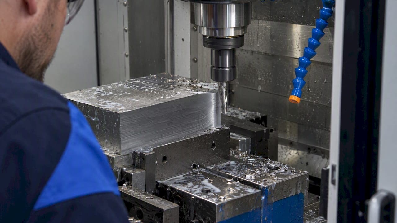
Limited-engagement work and thin-wall deflection research both back this approach, and our Chip Thinning calculator runs the numbers for you.
TL;DR:
- At 10% radial engagement, actual chip thickness is about 60% of programmed feed per tooth, so compensation raises feed by roughly two thirds.
- Use the correction formula only for 90 degree cutters; ball nose and lead angle tools need geometry specific factors, and units must remain consistent.
- For thin walls, lower engagement limits deflection; in micro milling, avoid chip thickness below roughly 0.20 to 0.40 times the cutting edge radius.
- Raise feed toward the corrected value in two or three steps, while checking spindle load, chatter, surface finish, controller limits, and engagement spikes in corners.
Table of Contents
- What radial engagement, feed per tooth, and chip thickness mean
- How chip thinning happens and how to compensate
- When radial engagement actually matters
- Toolpath strategies that reduce radial engagement
- How engagement and chip thinning affect forces, chatter, and tool life
- A step-by-step checklist to set and verify compensation
- Advanced tips for exit angle, runout, and stability
- How we support these calculations in your shop
- Why we put repeatability ahead of cycle time
- Run your own numbers with our calculators and Tool Crib
- FAQ
- Sources
What radial engagement, feed per tooth, and chip thickness mean
Before any compensation, make sure CAM, controller and calculator all use the same definitions.
- Radial engagement (ae): the radial depth of cut, or stepover, measured across the cutter diameter. Express it as a fraction or percent of diameter, so a cut can be expressed as a percentage of the cutter diameter.
- Feed per tooth (fz, IPT): the distance the cutter advances per flute per revolution. It maps to table feed with vf = fz × z × RPM, so confirm flute count and spindle speed before trusting any number.
- Maximum uncut chip thickness (hmax): the thickest point of the chip. In a slot it equals fz, but as ae drops below half the diameter, hmax falls below the programmed fz.
- Entering angle: Cutter geometry affects chip thickness, so use a formula suited to the cutter. Cutters with a lead angle, such as chamfer or high-feed designs, thin the chip further, so their formulas differ.
If you work in feed per revolution instead, our guide on converting fz, then adjusting covers the conversion.
How chip thinning happens and how to compensate
At low ae, the cutter engages a short arc. Each tooth enters the material at a shallow angle, so the chip it removes is thin at both ends and thickest in the middle, and that peak is lower than the fz you programmed. Run the programmed fz and the cutter rubs instead of cutting.
For a 90° cutter, the common correction is:
Corrected fz = target chip thickness ÷ √(1 − (1 − 2 × ae/D)²)
Here D is the cutter diameter. As ae decreases relative to D, the correction factor grows.
Worked example (illustrative numbers) using a 0.5 in. cutter:
- Compute 1 − 2 × 0.10 = 0.80, then square it: 0.64.
- Compute 1 − 0.64 = 0.36, and the square root is 0.60.
- Corrected fz = 0.002 ÷ 0.60 = 0.0033 in. per tooth.
- Table feed = 0.0033 × 4 × 8,000 = about 107 in./min, versus 64 in./min uncorrected.
Keep units consistent (inches or millimeters throughout) and always convert fz to machine feed before you key it in.
At ae near 10%, the chip is only about 60% as thick as programmed, so feed must rise by roughly two thirds to compensate. That follows directly from the geometry above, and our shop-floor write-up on fixing chip thinning to raise table feed shows the same effect in practice.
When radial engagement actually matters
Chip thinning becomes more relevant as radial engagement decreases, so consider compensation when using low ae. Production work often moves from 25–50% stepover to limited engagement of 5–10% of cutter diameter, paired with deeper axial cuts to lift metal removal rate and tool life while cutting side loads and heat.
Part stiffness changes the calculus. A 2024 PMC study found that on thin-walled or delicate parts, excessive radial forces cause deflection and static form errors, so feed scheduling and radial width of cut both need control. If you suspect deflection, our tool deflection calculator guide walks through it.
Quick decision rules:
- Check ae as a percent of diameter first; compensate when using low ae.
- Check part stiffness; thin walls favor lower ae regardless of chip thinning.
- Check cutter geometry; lead angles and ball noses need their own factors.
- Check whether micro-milling edge-size effects apply, which is the case when chip thickness approaches the cutting-edge radius.
Toolpath strategies that reduce radial engagement
Several path types hold instantaneous engagement low. Clemson dissertation work on nickel-based superalloys reports that trochoidal, circular and looping paths cut forces and extend tool life, at the cost of longer cycle time or a need for higher-end machine kinematics.
- Trochoidal milling: the tool moves in small circular arcs along the slot, so instantaneous ae stays low. It helps in complex pockets and corners, but short arc segments can stress older controllers.
- HEM, or limited-engagement roughing: low ae with high axial depth of cut. Side loads and heat drop because each flute spends more time out of cut between engagements.
- Circular looping: loops that clear material while keeping engagement more uniform than a conventional zigzag. It is a good fit for open areas where full trochoidal arcs would be slow.
- Ramping: a controlled entry into the cut. It manages the transition into full depth and should precede, not replace, an engagement-limited path.
On the CAM side, enable the chip-thinning toggle if your system has one, simulate engagement along the entire path, and check kinematic limits. Engagement can spike in corners, and fast engagement calculation methods exist for finding where.
How engagement and chip thinning affect forces, chatter, and tool life
Underfeeding at low ae causes rubbing and ploughing, which raises temperature and speeds flank wear. Overcompensating pushes the edge too hard, raising torque and risking chipping.
Stability matters too. Milling dynamics research ties chip width and spindle speed into stability lobe diagrams, and regenerative waviness is a primary driver of chatter. Because stability depends on chip width for a given machine and tool, changing ae shifts where your stable spindle speeds sit. Listen for pitch changes and watch spindle load during first cuts.
At the small end, micro-milling literature estimates minimum uncut chip thickness at roughly 0.20–0.40 of the cutting-edge radius for many alloys, and cutting below it ploughs instead of shearing.

Below that minimum chip thickness, material is pushed rather than cut, so overly aggressive compensation downward in ae can backfire in micro-milling.
A step-by-step checklist to set and verify compensation
- Pick a target chip thickness. Use your shop standard or the tool supplier's recommended chip load for the material.
- Calculate corrected fz. Apply the formula for your ae, then convert to table feed with vf = fz × z × RPM.
- Enter it in CAM or the controller. Either type in the corrected value or let a chip-thinning toggle do it. Confirm the stepover and simulated engagement match what you calculated.
- Run a short test cut. Watch spindle torque, listen for chatter, and inspect surface finish.
- Log the result. Record feed, speed, engagement and tool life so the next job starts from data.
Before the first run, also set safe feed ramps and check acceleration and jerk limits, since the higher feeds at low ae can outrun a controller's lookahead. Recording outcomes in a maintenance workflow helps too; this Italian-language guide on reducing micro-stoppages shows how a dedicated maintenance system can be structured.
Pro Tip: Raise feed in two or three steps toward the corrected value instead of jumping straight to it, and note the spindle-load reading at each step.
Advanced tips for exit angle, runout, and stability
- Manage exit angle. Practitioners note that exit angles roughly between -30° and +30° raise edge-chipping risk, so use roll-in and roll-out moves where you can.
- Check runout. Precision micro-milling research shows runout raises cutting force and wear because teeth engage unevenly, and low ae magnifies that effect. Our guide to tool runout effects covers how to measure and fix it.
- Test stability fast. Compare spindle-load variance or listen for audio changes across a short test, and stiffen the fixture if it shows up.
Pro Tip: Re-seat the tool in the holder and re-measure runout before blaming the feed.
How we support these calculations in your shop
Our platform includes a Chip Thinning calculator, Feeds & Speeds, Tool Deflection, and G-Code analysis. Our Tool Crib records tool life, so each tested value becomes a repeatable record. The workflow is simple: compute corrected fz, test a short cut, log the result, then iterate.

Why we put repeatability ahead of cycle time
We would take a steady chip thickness and a logged result over a few seconds of cycle time every time. A shop that skips compensation tends to find out the hard way, with a snapped endmill mid-pocket. The same pocket, rerun with a corrected feed and a note in the log, finishes without drama. Consistency is what keeps a machine running through the night.
— Availzye
Run your own numbers with our calculators and Tool Crib

Our platform includes a Chip Thinning calculator, Feeds & Speeds, Tool Deflection and Tool Crib. Start a free trial and run your own numbers, then log what you learn. You can see all plans and start your trial.
FAQ
What is radial engagement in milling?
Radial engagement, or ae, is how far the cutter sits into the material sideways, also called stepover. It is usually stated as a percent of cutter diameter. It controls how much of the flute is cutting at once.
At what radial engagement does chip thinning start?
At higher radial engagement, programmed fz is close to actual chip thickness. Below it, you need to raise feed or change the toolpath.
Is 10% radial engagement too low?
Not necessarily. Limited-engagement approaches often target 5–10% of cutter diameter, paired with higher axial depth of cut. You do need chip-thinning compensation at that level.
Does the chip-thinning formula work for ball nose cutters?
The formula shown here is for 90° cutters. Ball nose and lead-angle cutters have different effective entering angles, so use a calculator that accounts for tool geometry.
Sources
- Limited Engagement: Drilling Performance
- Numerical evaluation of cutting strategies for thin-walled parts
- Alternative Milling Path Planning Strategies and Force Modeling for Nickel-Based Superalloys
- doi:10.1016/S0022-460X(03)00119-6