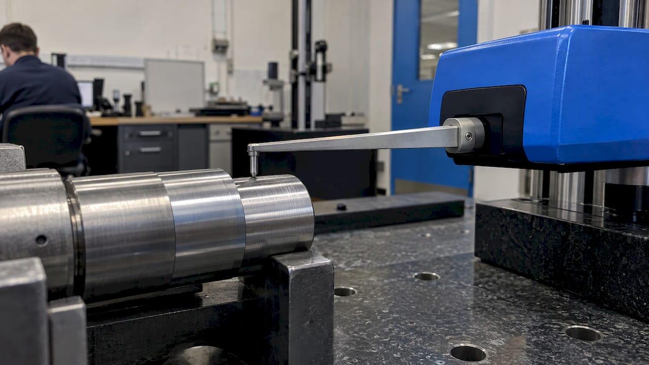
To measure surface finish on a machined part, drag a stylus profilometer across the surface at the right cutoff length. The instrument filters out waviness and reports roughness, usually Ra in microinches (µin) in the US, plus Rz and others. A calculator can estimate what a turning pass should produce, but only a measurement tells you what the part actually has. This guide covers the parameters, the instruments, the settings that decide whether your number is trustworthy, and how to read a callout on a drawing.
TL;DR
- Ra is the roughness average and the parameter most US drawings call out, in µin. One µm equals 39.37 µin.
- A stylus profilometer is the standard shop tool. The cutoff length you choose changes the number you get, so set it to match the drawing.
- A single Ra value on a drawing is a maximum. Smoother passes the part, but usually costs more.
- Calculators based on feed and nose radius give a best-case baseline for turning. Measured results are typically rougher.
- Log the parameter, cutoff, traverse direction and instrument with every reading so the result can be repeated.
Table of Contents
- Surface finish vs. surface roughness
- The parameters you will actually see
- Units: microinches and micrometers
- How surface roughness is measured
- Getting a number you can trust
- Reading a callout: what Ra 3.2 means
- Estimating finish with a calculator
- When the measurement is rougher than planned
- Our perspective
- Put the numbers to work
- FAQ
- Sources
Surface finish vs. surface roughness
The two terms get used interchangeably on the shop floor, but they are not the same thing. Surface texture is the whole picture: roughness, waviness and lay. Roughness is the fine, closely spaced irregularity left by the cutting tool. Waviness is the longer-wavelength component from things like machine vibration or deflection. Lay is the direction of the dominant pattern. In the US, the governing document is ASME B46.1, Surface Texture (Surface Roughness, Waviness, and Lay), an American National Standard.
"Surface finish" is the everyday word for the overall condition of the surface. "Surface roughness" is the measured part of it. When a customer says "I need a 32 finish," they almost always mean Ra 32 µin. For a deeper look at how roughness and waviness are separated, see our note on cutoff for waviness and roughness.

The parameters you will actually see
Ra: the one on most drawings
Ra is the average deviation of the roughness profile from the mean line. According to GD&T Basics, Ra is the parameter typically used in the United States, while Rz is common internationally. Ra is quick to understand, but it averages away isolated peaks and scratches, so two very different surfaces can share the same Ra.
Rz, Rq and Rt
Rz is built on maximum heights, not averages. Per GD&T Basics, the profile is divided into five equal lengths, the peak-to-valley height of each is taken, and Rz is the average of those five. Because it rests on extremes, Rz is almost always greater than Ra. The same source gives a rough rule: if you only know Rz, divide by about 7.2 to approximate Ra. Treat that as a ballpark, not a conversion for a drawing.
Rq (also called RMS) squares the deviations, averages them and takes the square root. Bal Seal Engineering notes it comes out about 11% higher than Ra for the same surface and reacts more to occasional highs and lows. If an older drawing calls out RMS, expect a number a bit above the Ra your instrument shows.
For a side-by-side look, see our Ra vs Rz guide.
Areal parameters: Sa and Sz
Profile parameters come from one line. Areal parameters such as Sa and Sz come from a full 3D map of an area. Polytec notes that the ISO 25178 framework behind them is increasingly specified in automotive, aerospace, semiconductor and medical device work. In a typical job shop you will still meet Ra far more often.
Units: microinches and micrometers

US drawings use microinches. Metric drawings use micrometers. ASME B46.1-2019 defines one microinch as 0.0254 µm, which is the same as saying 1 µm is 39.37 µin.
A quick reference for common values:
| Ra (µm) | Ra (µin) | Typical meaning |
|---|---|---|
| 0.4 | 16 | Ground, honed or very fine finishing |
| 0.8 | 32 | Fine turning or grinding |
| 1.6 | 63 | Standard CNC milling finish pass |
| 3.2 | 125 | General machined surface |
| 6.3 | 250 | Rough machining |
These process associations come from Mavlon's glossary. For typical ranges by process, Accurate Machine & Tool reports 16 to 125 µin for milling and 4 to 32 µin for grinding. It also points out that a drawing calling Ra 4 µin on a milled surface is really asking for grinding or polishing. Our Ra chart puts these ranges in a one-page reference.
How surface roughness is measured
Contact: the stylus profilometer
This is the instrument most shops own. Polytec describes a diamond-tipped stylus dragged across the surface at a very low force, typically around 1 mN. Its vertical movement is recorded as a 2D height profile, and parameters like Ra, Rz, Rq and Rt are calculated from it. NIST's tutorial lists the stylus technique among profiling methods, alongside optical profiling and others, all of which build a profile of height versus distance.
Portable units come in handy for checks at the machine. Handheld skid-type gauges give you an Ra reading quickly and suit production checks. Bench units with a separate datum give more flexible parameter sets and traverse lengths for inspection-room work.
Non-contact: optical methods
Optical profilers and laser scanners read the surface without touching it. They are useful on soft materials, delicate features, or when you want areal data. Whichever method you use, understand that the result is only as representative as the area measured. According to Polytec, a single 2D line on a heterogeneous or directional surface can give a misleading result.
Visual and tactile comparison
Roughness comparison plates let an operator match a surface by eye and fingernail. They are fine for a quick sanity check on the floor, but not for acceptance against a numeric limit.
Getting a number you can trust
A reading depends on setup. These are the settings that change the answer.
Cutoff and sampling length
Before any roughness number is computed, waviness is filtered out. NIST explains that the limiting wavelength is the cutoff, with available values of 0.08, 0.25, 0.8, 2.5 and 8 mm. Five cutoff lengths are normally used for assessment, and the total traverse is seven cutoff lengths.
ASME B46.1-2019 adds that the traversing length must be longer than the evaluation length because of end effects in profile measurements. This is why a very short land or narrow feature can be hard to measure: there may not be enough length to run a full evaluation.
For US shops working in inches, Bal Seal summarizes the ANSI B46.1-1978 guidance:
| Expected roughness | Sample length |
|---|---|
| 10 to 120 µin Ra | 0.030 in |
| Finer than that | 0.010 in |
| Below about 2 to 3 µin Ra | 0.003 in |
The 0.030 in length is about 0.8 mm, the most common cutoff for ordinary machined surfaces.
Direction and location
Measure across the lay, perpendicular to the tool marks, unless the drawing says otherwise. A trace parallel to the marks reads much smoother and flatters the part.
What the drawing says about testing
The drawing does more than set a limit. According to Polytec's guide to ISO 21920, it also sets the conditions for testing, including filter settings. Unless stated otherwise, the maximum rule applies: if a single measured value exceeds the specification, the sample is rejected. The 16% rule has to be requested explicitly.
A shop checklist
- Confirm the parameter and limit on the drawing (Ra, Rz, and in µin or µm).
- Set the cutoff and evaluation length to match, or use the drawing's callout.
- Clean the part and fixture the gauge so it cannot rock.
- Trace across the lay, in at least a few locations on the functional surface.
- Record the value, parameter, cutoff, direction, instrument and date.
Logging these details is what lets a second person, or you next month, repeat the reading and get the same answer.
Reading a callout: what Ra 3.2 means
Ra 3.2 means 3.2 µm, or 125 µin. On a drawing, one value is a ceiling. A Sekkei Genba Lab guide notes that the value is an upper limit by default with no lower limit implied, so a surface called out at Ra 3.2 can be much smoother and still comply. Going smoother is allowed, but it costs more machining time.
In practice, 3.2 µm suits brackets, housings, mounting plates and other non-critical surfaces. Yijin Solution reports it as the typical default at most CNC shops when no finish is called out.
Tolerance and finish are linked
Surface finish tolerance is not a separate dimension. It is the permitted roughness limit, and it interacts with size tolerance. Bal Seal advises that a diameter tolerance should be at least eight times the Ra value, otherwise roughness alone can eat the dimensional tolerance. For fits, see our ISO tolerance tables and press fit guide.
The Precision Machined Products Association makes the cost point plainly: finish should match the function of the surface, and fine textures the part does not need are expensive. It also points to ANSI/ASME B46.1 and Y14.36 for specifying finish.
Estimating finish with a calculator
Before you cut, you can estimate what a turning pass should deliver. A turning surface finish calculator uses feed per revolution and tool nose radius, as Kennametal's calculator page explains. The theoretical relationship is Ra ≈ f² / (32 × r), where f is feed per revolution and r is the nose radius. Larger radius and lower feed give a better theoretical finish.
A worked example: at 0.008 in/rev with a 1/32 in (0.03125 in) nose radius, f² is 0.000064, and 32 × 0.03125 is 1.0. Theoretical Ra is 0.000064 in, or 64 µin. Halve the feed to 0.004 in/rev and it drops to 16 µin, because feed is squared.
That number is a best case. The same Kennametal page lists what pushes real results away from theory: cutting speed and thermal effects, tool wear, built-up edge, machine rigidity and chatter, and material properties. The formula is for single-point turning. It does not describe milling, grinding or lapping.
So use the estimate to pick a starting feed and insert radius, then confirm with a measurement. Our scallop height guide covers the geometry in more depth, and the surface finish calculator runs it for you.
When the measurement is rougher than planned
If the gauge reads worse than the calculation, work through the usual suspects in order: tool wear or a chipped edge, built-up edge at low speeds, feed too low so the edge rubs instead of cutting, a loose setup or long overhang that lets the tool chatter, and the wrong insert geometry. Our surface finish troubleshooting guide shows how to read the marks, and how to improve surface finish covers the fixes.
Finish also matters beyond looks. A study on AlSi10Mg published in the Journal of Applied Research and Technology found a strong positive link between Ra and coefficient of friction during sliding. After 50 minutes of testing, a 20% increase in Ra produced a coefficient of friction 118.07% higher. For sliding or sealing surfaces, the number on the print is a functional requirement.
Our perspective
Most finish problems we see are not measurement problems. They are record-keeping problems. The reading was right, but nobody wrote down the cutoff, the direction or the insert that made it, so the next run cannot be compared.
That is why we built Availzye Machinist Pro to put calculation and shop records in one place. You estimate the finish from feed and nose radius, run the cut, measure, and log the result against the job, the tool and the machine. Next time, you start from your own data instead of a guess.
Our platform brings feeds and speeds, the surface finish calculator, a job tracker and tool life logging into a single cloud-synced application, so the numbers you calculate and the results you measure stay together.
Availzye
Put the numbers to work
If you want the estimate and the shop record in one tool, Availzye Machinist Pro includes a surface finish calculator, feeds and speeds, a job tracker and a tool crib. Plans are $9.99 CAD per month for Individual, $24.99 CAD per month for Small Shop and $49.99 CAD per month for Team, with a 7-day free trial.

See the plans and start your trial on the Availzye Machinist Pro site.
FAQ
What unit is Ra measured in?
In the US, Ra is normally given in microinches (µin), one millionth of an inch. The international unit is the micrometer (µm), and one micrometer equals 39.37 µin, per GD&T Basics. Check the drawing, since both appear in practice.
How do I measure Ra on a machined part?
Use a stylus profilometer, set the cutoff the drawing requires (often 0.030 in or 0.8 mm for typical machined surfaces), and trace across the lay. Take readings at several locations on the functional surface. Record the parameter, cutoff and instrument along with the value.
What does a 3.2 surface roughness mean?
It means a maximum Ra of 3.2 µm, which is 125 µin. A smoother surface still complies, but may cost more to produce. It is a common finish for general machined surfaces such as housings and mounting plates.
Can a calculator tell me my finished Ra?
It can give a theoretical baseline for single-point turning from feed and nose radius. Real results usually come out rougher because of wear, built-up edge, vibration and material. Use the estimate for planning, and measure the part for acceptance.
Sources
- ASME B46.1 Surface Texture catalog page
- The Basics of Surface Finish, GD&T Basics
- Measuring Surface Finishes, Bal Seal Engineering
- Stylus or optical profiler, Polytec
- ASME B46.1-2019 Surface Texture Standard
- Mavlon, Surface Roughness (Ra) glossary
- How to Specify Surface Finish on a Drawing, Accurate Machine & Tool
- Surface finish metrology tutorial, NIST
- Roughness evaluation according to ISO 21920, Polytec
- Surface Roughness Symbols on Engineering Drawings, Sekkei Genba Lab
- CNC Machining Surface Roughness guide, Yijin Solution
- Designer's Guide: Surface Texture (Finish), PMPA
- Surface Finish Calculator, Kennametal
- Journal of Applied Research and Technology, v22n2