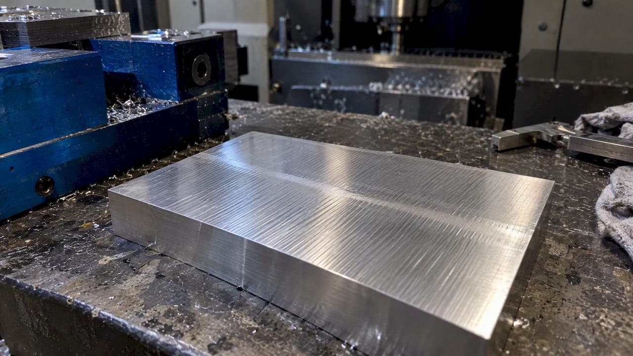
When a part holds every dimension but the surface looks wrong, the marks usually tell you the cause. Repeating waves point to vibration. Smeared or torn metal points to built-up edge or a rubbing tool. A pattern that matches your stepover points to the toolpath. A shiny, dragged look near the end of a run points to wear. Work through those clues in order and you will usually find the problem in a few test cuts instead of a day of guessing.
This guide is for machinists, operators and shop owners who run real jobs and need to get a part past inspection. It covers how to read what is on the part, which checks to do first, what the numbers on the print mean, and how to keep the fix from drifting back.
TL;DR
- Identify the mark before changing anything: chatter, feed lines, smearing, re-cut chips and wear each have a different fix.
- Check the cheap mechanical causes first: tool overhang, holder runout, workholding and chip evacuation.
- Slowing down does not cure chatter. Change spindle speed by roughly 10 to 15% or use a variable-helix tool instead.
- Confirm the print callout (Ra or Rz) and measure with a calibrated instrument before you declare a part good or bad.
- Log what fixed it, so the next job on that material starts from a known-good setup.
Table of Contents
- Read the surface before you touch the program
- Start with the print: what is actually being asked for
- Make sure the measurement is trustworthy
- Fix 1: Get the chips out of the cut
- Fix 2: Break the chatter cycle
- Fix 3: Deal with deflection and overhang
- Fix 4: Measure runout, do not assume it
- Fix 5: Look at the cutting edge itself
- Fix 6: Feed, speed and built-up edge
- Fix 7: When the toolpath is the problem
- Our perspective: troubleshoot one variable at a time
- Put the checks and the numbers in one place
- A ten-minute order of checks
- What good records look like
- FAQ
- Sources
Read the surface before you touch the program
Most wasted time in finish problems comes from changing feed and speed when the cause is mechanical. Put the part under a light, tilt it, and match what you see against this table.
| What you see | Most likely cause | First action |
|---|---|---|
| Repeating wave pattern, often with a squeal, not matching the feed | Regenerative chatter | Change spindle speed 10 to 15%, shorten the tool |
| Chatter only in deep pockets or tall walls | Too much tool stick-out | Shorter or larger-diameter tool |
| Regular lines at the same spacing as the feed or stepover | Feed per tooth too high, or scallops from the toolpath | Lower feed on the finish pass, tighten stepover |
| One flute leaves a heavier mark, uneven pattern around the cut | Holder or collet runout | Re-seat the tool, clean the taper, measure runout |
| Smeared, torn or dull-looking surface, flakes of material welded on | Built-up edge or rubbing | Adjust speed and feed, check coolant and tool geometry |
| Scratches or swirl marks in pockets | Chips being re-cut | Air blast or high-pressure coolant, change the cutting direction |
| Good at the start of a run, worse over time | Flank wear | Index or replace the tool |
The chatter row follows a published chatter diagnosis checklist, and the same source makes the key distinction: chatter marks are wave-like and repeat at frequencies unrelated to the programmed feed rate, while feed lines follow the feed. If the spacing of the marks changes when you change feed, you are looking at feed marks. If it does not, think vibration.
Start with the print: what is actually being asked for
Before chasing a number, make sure you know which number. Surface texture is made of roughness, waviness and lay, but drawings often specify only roughness. The ASME B46.1 poster defines Ra as the arithmetic average of the absolute profile height deviations from the mean line over an evaluation length. Rz is different: it looks at the distance between peaks and valleys across several sampling lengths, so it reacts much more to a single deep scratch or tall peak.
That difference matters when you troubleshoot:
- A part can pass Ra and fail Rz if one flute or one chip mark leaves an isolated groove.
- Rz is often preferred for sealing surfaces and stress-critical parts where peak heights matter, as noted in the research behind this guide.
- A callout of Ra 25 means 25 µin, about 0.63 µm, a standard commercial finish that most milling or turning processes can reach.
Do not convert between Ra and Rz with a fixed multiplier. Guidance on surface roughness points out that the two measure different properties, so rules like Rz = 4 x Ra are rough approximations and can cause inspection failures when you rely on them for print compliance. If you need a refresher on the relationship, see our Ra vs Rz guide, and keep the Ra chart near the machine for quick reference.
Make sure the measurement is trustworthy
Half of the "bad finish" arguments between shop and customer are really measurement arguments. Instruments differ in stylus force, filter and cutoff length, and a discussion of measurement disagreement notes that each method can carry a slight bias, so results from two devices may not match.
A few habits settle most of it:
- Use the same instrument, filter type and cutoff the customer uses. ASME B46.1 exists to give both sides a common language and method for instrument settings, Gaussian filters and cutoff lengths.
- Verify the instrument against a certified reference specimen. In the US that means NIST-traceable specimens; without that, readings are unreliable for quality control.
- Measure across the lay, not along it, and measure in more than one spot.
- Write the reading, the instrument and the settings on the inspection record.
Only after the numbers are credible should you start changing the process.
Fix 1: Get the chips out of the cut
If a pocket looks scratched or hazy and the part is within tolerance, suspect chips first. Hurco's shop guidance describes re-cut chips as a common cause of poor finish even when every dimension is good, and practitioners often find that clearing chips with high-pressure coolant or an air blast is the most effective first fix, especially in pockets and interrupted cuts where chips get trapped.
What to try, in order:
- Point the coolant nozzle or air blast at the cutting zone, not at the tool shank.
- In deep pockets, add a ramp or helical entry so chips have somewhere to go.
- Reduce the width of cut on the finish pass so chips are thinner and easier to evacuate.
- Check that the flute count suits the material: a gummy material with too many flutes packs the flute space.
- Change direction of travel if chips are being pushed into an already-cut wall.
This is the cheapest test in the shop. It takes a few minutes, needs no program change and often tells you whether to keep looking at chips or move on to vibration.
Fix 2: Break the chatter cycle
Chatter is the cause people most often treat wrongly. The instinct is to slow down. But chatter is regenerative vibration, and, per the same chatter guide, it often calls for a change in RPM of around 10% or the use of variable-helix tools to break the harmonic cycle. Slowing the feed alone can leave the tool rubbing and make marks worse.
A practical sequence:
- Shorten the tool. Pull it out of the holder as little as you can. The checklist from that guide points to excessive overhang when chatter shows up only in deep pockets.
- Change spindle speed. Try 10% up, then 10% down, with the feed per tooth held constant so you change one thing only. Listen for the squeal to drop out.
- Switch tool geometry. Variable-helix or variable-pitch end mills disturb the repeating pattern that feeds regenerative chatter.
- Check workholding. Hurco's guidance says to confirm that workholding is solid and not promoting harmonic issues or vibration. A thin wall that is not supported will sing no matter what the tool does.
- Reduce radial engagement before reducing speed. A lighter radial cut lowers force without cutting your productivity as hard.
If you want a structured way to find stable speeds instead of trial and error, our walkthrough on stability lobe checks for milling chatter shows the method.
Fix 3: Deal with deflection and overhang
A tool that bends is a tool that cuts a different surface than the one you programmed. Long, small-diameter tools, tall walls and heavy radial cuts all push the tool away from the work, then let it spring back, leaving taper, steps or witness lines between passes. Hurco's guidance advises that we ensure we are not using unnecessarily long tooling that can deflect easily.
Simple ways to reduce it:
- Use the shortest tool that reaches the feature, and the largest diameter that fits.
- Take a spring pass (a second finish pass at the same offset) on critical walls.
- Split the finish: rough to leave a small, even stock, then finish with light, consistent engagement.
- Avoid full-width slotting for finishing; use a lighter radial engagement.
If you want numbers instead of feel, run the tool through the tool deflection calculator with the actual stick-out, diameter and cutting force. We also explain the reasoning in our piece on stopping scrapped parts with deflection calculations.
Fix 4: Measure runout, do not assume it
Runout is the cause people most often skip because the tool "looks fine" in the holder. Harvey Performance's technical guidance says even runout as small as 0.001" makes one flute do far more work than the others. That raises cutting forces, shortens tool life and works against a good surface, especially with small or high-precision tools.
A quick runout routine:
- Clean the spindle taper and the holder. Chips or film here cause more runout than a worn holder.
- Seat the tool, tighten to the holder maker's spec and indicate near the tip.
- Re-seat and re-measure if it is off. Turning the tool in the holder sometimes cancels the error.
- If the problem persists, try a different collet or holder before blaming the spindle.
Our article on tool runout effects on the shop floor goes deeper on how to quantify what runout costs you in tool life.
Fix 5: Look at the cutting edge itself
Tool wear is both a cause and a symptom. As the flank wears, the cutting geometry changes and forces and heat rise. Sandvik Coromant's milling troubleshooting guide covers wear alongside vibration, chip jamming and unsatisfactory finish. The shop-floor takeaway: if the finish deteriorates quickly during a run, check the edge before you touch parameters. The tool may simply be at the end of its life and need indexing or replacement.
What to do with that:
- Inspect the edge under magnification when the finish starts to degrade.
- Record how many parts or minutes a finishing tool gives you before the finish drifts, then change it ahead of that point.
- Dedicate a fresh tool to finishing passes. A tool that is too worn for roughing can still look acceptable, but it will not hold a finish.
Tracking tool life is the part most shops skip. Without it, you only learn about wear when a part gets rejected.
Fix 6: Feed, speed and built-up edge
When the surface looks smeared or torn rather than wavy, built-up edge may be welding material onto the cutting edge and tearing it away. Xometry's guide to avoiding poor finishes lists chatter, tool deflection, built-up edge and chip re-cutting as the primary causes, and notes that in finishing, lower feed rates combined with higher spindle speeds are a common way to cut contact time and reduce built-up edge.
For tools with wiper flats, the same source recommends keeping feed per revolution below 70 to 80% of the wiper land width. Feed beyond that wastes the wiper and leaves the feed lines you were trying to remove.
A note on thin chips: at light radial engagement, the actual chip is thinner than the programmed feed suggests, and a tool that is rubbing instead of cutting leaves a poor surface. If your finish pass uses a very light step-over, check whether you need to raise the feed to compensate. Our article on fixing chip thinning covers that adjustment, and our guide to calculating feeds and speeds walks through the base numbers.

Fix 7: When the toolpath is the problem
Some finish problems come from the program, not the machine. If the pattern lines up exactly with your stepover, or you see faceting on curved surfaces, look at:
- Scallop height. Tighter stepover on 3D surfaces reduces the ridges between passes, at the cost of cycle time.
- Chordal tolerance. A loose tolerance in CAM turns arcs into short straight segments, which can show up as faceting.
- Direction changes and retracts. Many small moves make the machine hesitate and leave marks at each blend.
- Climb versus conventional milling. Pick based on the material and the machine, and keep it consistent across the finish pass.
- Cutter compensation. A wrong offset leaves a step where the finish pass meets the rough wall. See our note on controller CRC versus CAM offsets.
Our guide to toolpath optimization explains how to cut cycle time first and then tune scallops, so you do not pay for finish with time you did not need to spend.
Our perspective: troubleshoot one variable at a time
The pattern we see in shop math is that finish problems get fixed slowly because several things are changed at once. The operator drops the feed, bumps the speed, swaps the tool and re-clamps the part, and the problem goes away. Nobody knows which change did it, so the same problem returns next month on a different job.

We built Availzye Machinist Pro around the idea that the calculation and the shop record belong in the same place. The deflection, chip thinning, power and chatter tools tell you what the physics predicts before you cut. The tool life log and job tracker tell you what actually happened. When those two agree, you stop guessing. When they disagree, that gap is where the answer lives: a holder with runout, a tool past its useful life, a wall that is less rigid than the model assumed.
Our advice is simple. Change one variable per test cut. Write down the result. Keep the winning setup attached to the material, the tool and the machine. A finish problem solved once should never have to be solved from scratch again.
— Availzye
Put the checks and the numbers in one place
If you troubleshoot with a calculator in one app, a spreadsheet for tool life and a notebook for what worked, the information rarely meets when you need it. Availzye Machinist Pro puts the feeds and speeds, tool deflection, chip thinning and chatter tools next to the Job Tracker, Tool Crib and tool life logging in one cloud-synced application. Plans are Individual at 9.99 CAD per month, Small Shop at 24.99 CAD per month and Team at 49.99 CAD per month, each with a 7-day free trial. You can compare them on the Availzye Machinist Pro plans page, or log finishing-tool wear in the Tool Crib.
A ten-minute order of checks
When a part comes off with a bad finish and you do not yet know why, work through this list. Each step is cheap, and most of them need no program change.
- Look at the pattern. Does the spacing follow the feed or stepover, or is it unrelated to it?
- Confirm the print. Ra or Rz, which value, which instrument settings.
- Measure properly. Calibrated instrument, across the lay, more than one spot.
- Clear the chips. Air blast or coolant aimed at the cut.
- Check the edge. Magnify it. Replace if wear is visible.
- Check runout. Clean taper, re-seat, indicate.
- Shorten the tool. Reduce overhang before anything else.
- Check workholding. Is the part or a thin wall free to move?
- Change spindle speed by 10 to 15%. Only the speed, with feed per tooth held.
- Then adjust feed and stepover. Lower the finish-pass feed, review wiper ratio and scallop height.
The order matters. Steps one to eight cost almost nothing and fix most problems. Parameters come last because they are the easiest to change and the easiest to change wrongly.
What good records look like
A useful finish record is short. For each material and tool, capture:
- Tool type, diameter, stick-out and holder
- Spindle speed, feed per tooth, axial and radial engagement
- Coolant or air method
- Measured Ra or Rz, with the instrument and cutoff
- Parts or minutes on the tool when the finish started to drift
With that, your next quote and your next setup begin from facts. It also makes disputes with customers easier to settle, since you can show the measurement method and the process behind the part. For a broader look at the process side, see our article on how to improve surface finish on machined parts.
FAQ
Why does my surface finish get worse when I slow the feed down?
A very low feed can make the tool rub instead of cut, especially at light radial engagement, which smears the surface and wears the edge faster. If the marks are wave-like and unrelated to the feed, you are probably dealing with chatter, and slowing down will not break the cycle. Try changing spindle speed by about 10 to 15% or shortening the tool first.
How do I tell chatter marks from feed lines?
Feed lines are regular and match your feed or stepover, so they change when you change the feed. Chatter marks are repetitive, wave-like patterns that occur at frequencies unrelated to the programmed feed rate. Chatter also tends to come with a high-pitched squeal or a noticeable change in sound.
What is the difference between Ra and Rz?
Ra is the arithmetic average of profile height deviations from the mean line over an evaluation length. Rz measures the distance between the highest peak and lowest valley over several sampling lengths, so it is more sensitive to isolated scratches and peaks. There is no exact conversion between them, so use the value the drawing calls out.
Why do I get a good finish at the start of a run and a poor one later?
This usually points to flank wear. As the edge wears, cutting forces and heat increase and the surface degrades. If the finish drops off quickly, check the edge and replace or index the tool before changing machine parameters.
Sources
- Xometry: How to Avoid Poor Surface Finishes on Machined Parts
- ASME B46.1-2019 poster: Surface Roughness, Waviness, and Lay
- ASME B46.1 overview on Nimonik
- Chatter in Machining: Causes, Chatter Marks, and Fixes
- Sandvik Coromant: Milling troubleshooting
- Harvey Performance: Optimized Machining With Miniature End Mills
- Surface Roughness Guide: Ra Rz, ISO 21920
- Hurco: CNC Machining, Improving Workpiece Surface Finish
- Deterco: Finding Common Ground for Measurement Disagreement