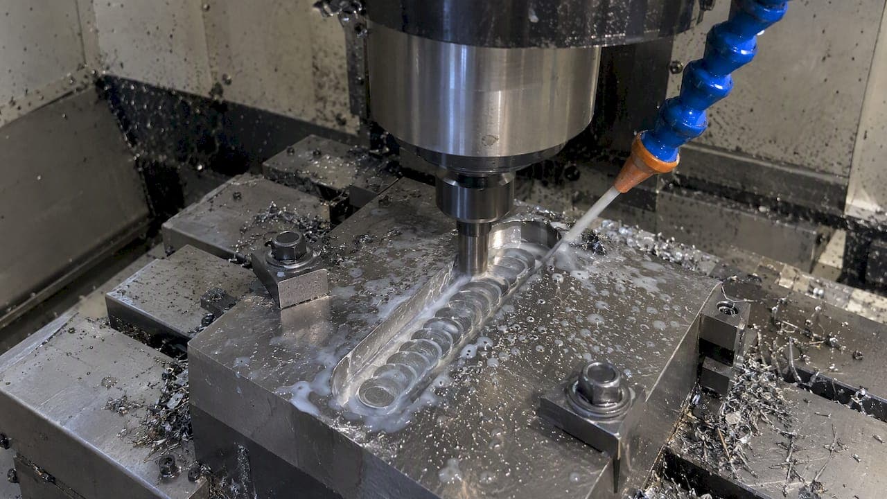
Trochoidal milling works when you hold radial engagement low, use the full flute length axially, and raise the feed to make up for chip thinning. Most of the parameters follow from those three decisions. Get the radial depth of cut wrong and the other numbers will not save the tool. Get it right and you can run a cutter harder, cooler and longer than a conventional slot would allow.
This guide walks through each parameter in the order you set it, with a worked example, the controller and coolant limits that catch shops out, and the mistakes that show up on the floor.
TL;DR
- Keep radial depth of cut (ae) at roughly 5% to 20% of cutter diameter and use axial depth (ap) up to about 2 times diameter, per Sandvik Coromant.
- Raise the table feed with a chip thinning multiplier. At 10% radial engagement it is about 1.7x, and at 2% it approaches 3.6x.
- Surface speed can go well above conventional slotting because the cutter spends most of each revolution out of the cut. Chip evacuation decides how far you can push it.
- Your controller's look-ahead and your coolant delivery are parameters too. Both can erase the gain from a perfect toolpath.
- Start conservative, listen to the cut, and log what works for each material and tool.
Table of Contents
- What trochoidal milling changes about the cut
- The parameters, in the order you set them
- A worked example
- What tool life and cycle time gain to expect
- The parameters most guides skip
- Starting-point table
- Common mistakes
- Our perspective
- Doing the math in one place
- FAQ
- Sources
What trochoidal milling changes about the cut
In a conventional slot, the cutter is buried in material on both sides. Heat has nowhere to go, chips are packed into a narrow channel, and the tool sees full-width engagement the whole way. A trochoidal path replaces that with a series of overlapping circular moves that advance along the slot. Sandvik Coromant describes it as circular milling with simultaneous forward movement, removing repeated thin slices of material.
The benefits come from the short arc of contact. The cutting edge is in the material for a brief portion of each turn, then cools. Cutting forces stay consistent instead of spiking at entry. Harvey Performance lists trochoidal milling as a form of high efficiency milling, which is a useful frame: the strategy and the parameters belong together.

That strategy matters as much as the numbers. A study indexed on PubMed Central on adaptive high efficiency milling points to consistent tool contact as the main mechanism behind lower wear in exotic alloys. If your toolpath lets the engagement angle jump at corners, no feed setting will fix it.
The parameters, in the order you set them
1. Radial depth of cut (ae)
This is the parameter that governs everything else. The published range is 5% to 20% of tool diameter. For a 1/2" endmill that is 0.025" to 0.100".
How to choose within that range:
- Soft, free-cutting materials (aluminum, mild steel): the upper end, 15% to 20%, if the machine has the power and the tool is short.
- Stainless and mid-hardness alloy steels: 8% to 12% is a sensible starting window.
- Titanium and thin-wall work: go lower. One titanium manufacturing source describes 5% to 8% radial engagement to cut cutting forces by 40% to 60% against conventional slotting in thin-wall structures.
- Hardened steel: trade press describes trochoidal paths as a good fit for hard milling in the mid-40s to mid-50s HRC range, but check your tool maker's data for the specific grade and coating.
Smaller ae lets you use more of the tool axially and reduces heat, but it lengthens the toolpath. There is a point where more passes cost more time than the feed gain returns. Typically that is below about 5%.
2. Axial depth of cut (ap)
Because the radial load is light, you can use the flute length. Sandvik gives up to 2x diameter as an upper figure. In practice, the limit is usually tool deflection and chip evacuation, not power.
Two checks before committing to a deep ap:
- Stick-out and deflection. A long, slender cutter at 2xD axial depth bends. Run the numbers in a tool deflection calculator before you cut, especially if the finish pass will be left to the same tool.
- Chip room. Deep slots with narrow width trap chips. If you cannot clear them, back off ap before you back off feed.
3. Slot width and path radius
The width of the slot minus the cutter diameter sets how much room the loop has. Hand-programming references typically set the loop arc as a fraction of the cutter diameter, and CAM systems expose this as a "loop radius" or "trochoidal radius." Keep the loop large enough that the tool does not turn tighter than the engagement you designed for. A tight loop inside a narrow slot quietly raises the real engagement above your ae setting.
Also confirm the stepover per loop (the forward advance for each circle). It should equal your intended ae, not exceed it. That is the detail that gets lost between a hand calculation and a CAM default.
4. Chip thinning and the feed multiplier
When ae falls below half the diameter, the chip is thinner than your programmed feed per tooth suggests. If you do not correct for this, the tool rubs instead of cutting. Harvey Performance explains that failing to adjust the feed rate leads to rubbing, premature wear and poor finish.
The correction is geometric. For ae under half the diameter D:
Feed multiplier = D / (2 × √(ae × (D − ae)))
| Radial engagement (ae / D) | Feed multiplier |
|---|---|
| 20% | 1.25x |
| 15% | 1.40x |
| 10% | 1.67x |
| 5% | 2.29x |
| 2% | 3.57x |
These match the range a tool maker publishes: about 1.7x to 1.8x at 10% and up to 3.6x at 2%, depending on the tool. Use the tool maker's own table when one exists, because corner radii and edge preps shift the true chip thickness slightly.
We cover the arithmetic in more depth in our guides on fixing chip thinning and chip load calculation.

5. Feed per tooth and table feed
Start from the chip load the tool maker recommends for the material at full-width or half-width engagement. Multiply that by the chip thinning factor to get your adjusted feed per tooth. Then:
Table feed (ipm) = adjusted fz × number of flutes × RPM
If you move between feed per tooth and feed per revolution when reading catalogs, our note on converting fz and feed per rev saves a common unit error.
6. Surface speed and RPM
Here trochoidal milling surprises people. Many operators assume higher SFM always means more wear. Sandvik's guidance is that the short engagement lets you run cutting speeds far above conventional methods, up to several times higher, because the edge stays cooler, as long as chips are cleared.
In practice, raise speed in steps from the tool maker's recommendation. Watch the chip color and the sound. Blue chips in steel or a rising spindle load at the same feed tells you that you went too far. For the baseline calculations, see our shop-ready feeds and speeds guide.
A worked example
This is an illustration of the method, not a recommendation for your tool or material. Always confirm against your tool maker's data.
Setup: 1/2" carbide, 5-flute endmill, cutting a slot in a stainless steel part.
- Choose ae = 10% of D = 0.050".
- Choose ap = 1.0" (2xD) if stick-out and chip evacuation allow.
- Say the tool maker's chip load at half-width engagement is 0.002" per tooth.
- Multiplier at 10% ae is 1.67, so adjusted fz = 0.002 × 1.67 = 0.0033".
- Pick a starting surface speed of 400 SFM. RPM = (400 × 3.82) / 0.5 ≈ 3,050.
- Table feed = 0.0033 × 5 × 3,050 ≈ 51 ipm.
That 51 ipm is the feed along the toolpath at the cutter's engagement, and it is much faster than a conventional slot feed for the same tool would be. On a machine that can sustain it, that is where the cycle time comes from.
Now the checks: does the controller keep that feed through short arcs, does the coolant clear the slot, and does the deflection stay acceptable? The next sections cover those.
What tool life and cycle time gain to expect
Reported figures vary by material and setup, so treat them as ranges. One supplier analysis of deep cavities in steel and stainless reports three to five times longer tool life than traditional slotting, and net cycle times on deep pockets that are typically 10% to 30% shorter. Those are supplier-reported results, not guarantees. Your gain depends on rigidity, coolant, and how well the toolpath maintains engagement.
The parameters most guides skip
Controller look-ahead
A trochoidal path is thousands of short linear moves. If the control cannot read ahead fast enough, it decelerates between blocks and you get stuttering and dwell marks, which wastes the feed rate you calculated. One source advises checking that your controller has high-speed look-ahead, citing a block processing rate under about 1,000 blocks per second as a risk, with high-end Fanuc and Siemens controls given as examples.
Before you run a long program:
- Check your control's look-ahead settings and high-speed machining mode.
- Ask your CAM post to output arcs (G2/G3) instead of tiny line segments where the control handles them better.
- Run an air cut and watch the actual feed readout in the arcs.
If you edit or inspect toolpath code by hand, our G-code generator helps with checking the arithmetic behind arc and feed lines.
Coolant delivery
Flood coolant often cannot reach the bottom of a deep trochoidal slot. A machining insights page recommends through-tool coolant at about 70 bar or higher for titanium and stainless, because it flushes chips out and prevents recutting, which is a fast route to tool failure. If you do not have through-spindle coolant, use air blast or a directed nozzle and reduce ap until chips clear.
Tool geometry
For difficult materials, look for tools made for trochoidal work. A titanium machining guide suggests unequal flute spacing and helix angles around 30° to 45° to break up harmonics and lift chips out. Tool makers also publish endmills designed for low radial engagement and full length of cut, with chip splitters for evacuation. Match the tool to the strategy rather than using a general-purpose cutter.
Climb direction
Trochoidal paths generally run climb milling so that chips are thin at exit and heat leaves with the chip. If you want the reasoning for the direction choice, see our piece on climb versus conventional milling.
Corners and entry
This is where engagement jumps. A good toolpath rolls into the slot instead of plunging straight to full width, and slows or adds more passes at inside corners. Check the simulation for any spots where the engagement angle spikes, since those moments cause most breakage.
Starting-point table
These are conservative starting windows for planning only. They combine the published ranges above with common practice, so confirm against your tool maker's recommendations.
| Material situation | ae (% of D) | ap | Notes |
|---|---|---|---|
| Aluminum, free-cutting | 15% to 20% | Up to 2xD | Check chip evacuation, limit by rigidity |
| Carbon and alloy steel | 8% to 15% | 1.5xD to 2xD | Use the multiplier table |
| Stainless steel | 8% to 12% | 1xD to 2xD | Coolant and sharp edges matter |
| Titanium | 5% to 8% | 1xD to 1.5xD | Through-tool coolant, steady engagement |
| Hardened steel | 5% to 10% | Lower than soft materials | Rigidity and tool grade decide |
Common mistakes
- Forgetting the multiplier. Running chip load as if it were a full-width cut. The result is rubbing, heat and poor finish.
- Setting ae in CAM and not checking the real engagement. Tight loops and corners raise it.
- Using too long a tool. Deflection ruins accuracy and invites chatter.
- Ignoring the machine. A slow controller turns a fast toolpath into a slow one.
- Not logging results. The best parameters for your machine are the ones you recorded last time.
If your toolpaths feel inefficient even with good parameters, our notes on toolpath optimization and high feed milling cover related strategies.
Our perspective
We build calculators for people who run real jobs, and the pattern we see is the same: trochoidal milling fails in the details around the numbers, not in the numbers. A shop gets a feed multiplier right, then loses the gain to a controller that stutters, or to a cutter with too much stick-out. Another shop never records what worked, so every new job starts from the catalog again.
Our advice is to treat parameters as a chain. Engagement sets chip thinning. Chip thinning sets feed. Feed and speed set spindle load. Deflection and coolant set whether the tool survives. Calculate each link, then write down the result next to the job, the material and the tool. The second time you cut that part, you start from proof instead of a guess.
— Availzye
Doing the math in one place
If you are repeating this calculation across jobs, a spreadsheet and a paper log get messy fast. Availzye Machinist Pro puts the feeds and speeds, chip thinning, tool deflection and power calculators in one cloud app, alongside a job tracker and tool crib for the shop side. Plans start at $9.99 CAD per month for Individual, with Small Shop at $24.99 CAD per month and Team at $49.99 CAD per month, and there is a 7-day free trial, so you can test it on a real slot before you commit.
FAQ
What radial depth of cut should I use for trochoidal milling?
Most published guidance puts it between 5% and 20% of the cutter diameter. Use the low end for titanium, thin walls and hard materials, and the higher end for aluminum and free-cutting steels. Adjust based on rigidity and what the spindle load tells you.
How much should I increase the feed rate?
Multiply the recommended feed per tooth by the chip thinning factor for your engagement. At 10% radial engagement that is about 1.67x, and at 5% about 2.29x. Confirm with your tool maker's table, since tool geometry shifts the exact value.
Can I run trochoidal milling on any CNC machine?
You can run it on most machines, but results depend on the controller. Trochoidal paths contain many short segments, so weak look-ahead makes the machine slow down and lose the advantage. Test with an air cut and watch the actual feed.
Do I need through-tool coolant?
It is not strictly required, but it helps a lot in deep slots and difficult materials like titanium and stainless. Flood coolant often cannot reach the bottom of the cut, so chips get recut. Without through-tool coolant, use air blast and reduce axial depth.
Is a higher cutting speed safe in trochoidal milling?
Often yes, up to a point. The cutter is in the material for only a short arc, so the edge runs cooler than in a full slot. Raise speed in steps, and stop when chips discolor or spindle load climbs.
Sources
- Sandvik Coromant: Slicing and trochoidal milling
- Harvey Performance: Intro to Trochoidal Milling
- Harvey Performance: How to Combat Chip Thinning
- PubMed Central: adaptive high efficiency milling study
- Kennametal: KOR5 DA radiused 5-flute endmill
- Trochoidal milling vs slotting: deep cavity tool life and cycle time
- Titanium manufacturing insights
- UFOR: Titanium machining technologies and strategies
- Modern Machine Shop