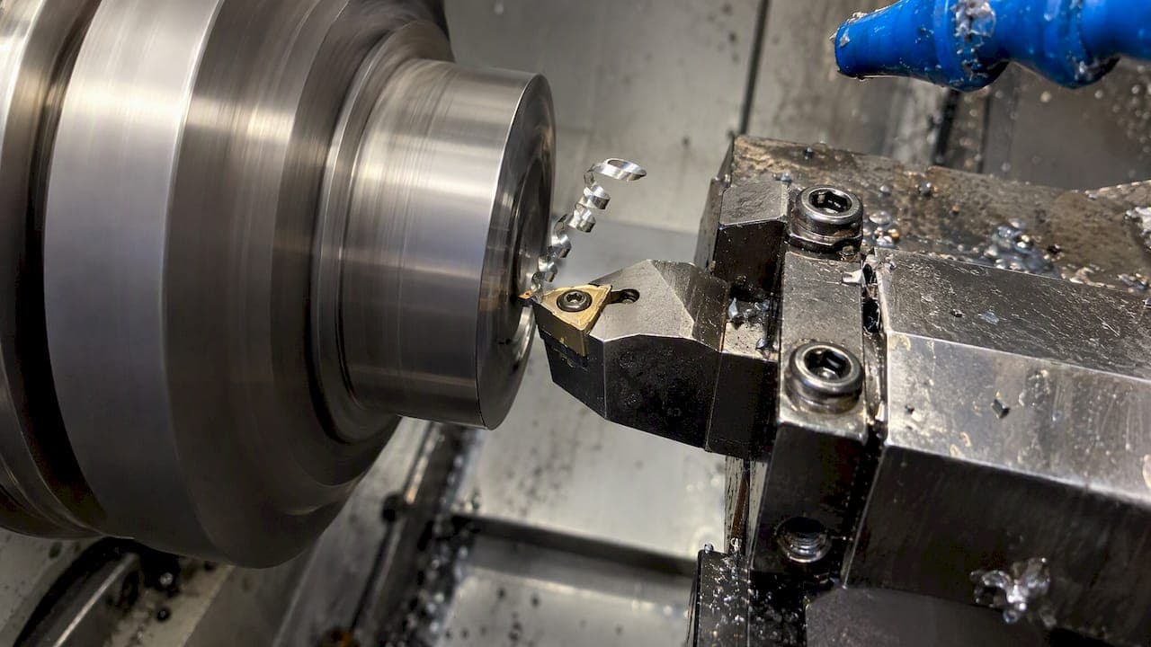
Chip evacuation problems come down to one thing: chips that stay in the cut longer than they should. They get recut, pack into a pocket, wrap the tool or clog a drilled hole. The fix is rarely just more coolant. It is usually a mix of chip size, tool geometry, toolpath and how coolant or air is delivered, and you can diagnose most cases from the chip itself and the sound of the cut.
This guide walks through how to recognize the problem, what causes it in milling, drilling and turning, how to choose a chip breaker, and how to stay safe while clearing chips.
TL;DR
- Look at the chips first. Stringy means too thin or the wrong breaker. Packed, welded or blue means they are not leaving the cut.
- In pockets and slots, toolpath beats coolant volume. Helical or circular ramping and sensible engagement do more than turning up the pump.
- In holes, geometry and cycle matter: flute helix, through-coolant and pecking depth all change whether chips exit.
- Pick a turning chip breaker by material and operation (finishing, medium, roughing), then confirm your feed and depth of cut sit inside its working window.
- Keep air blast under 30 psi for manual cleaning, never clear chips by hand, and mind metalworking fluid mist.
Table of Contents
- How to spot a chip evacuation problem
- Why chips fail to leave the cut
- Milling: pockets, slots and cavities
- Drilling: where depth decides everything
- Turning: chip breaker selection
- Aluminum versus stainless: different problems
- Coolant, air and safety when clearing chips
- Our perspective: treat evacuation as something you predict
- Put the numbers in front of you
- A troubleshooting order that saves tools
- FAQ
- Sources
How to spot a chip evacuation problem
Poor evacuation shows up in the part before it shows up in the chip bin. Chip recutting, chatter, smearing and visible clogging in deep pockets or holes are the typical signs, and they tie directly to broken tools and lost dimensional accuracy.
A quick checklist at the machine:
- Scratches or a hazy, torn finish on the wall. Chips are being dragged or recut between the tool and the part.
- Chips that look crushed, welded or discolored. They were cut twice, or cooked in the flute.
- Long, stringy ribbons around the tool or holder. Chip breaking is not happening. This is a chip formation problem first and an evacuation problem second.
- Load spikes or a change in sound at depth. Chips are packing and force is rising.
- A sudden tool break a few seconds into a deep move. Often a chip-packed flute, not a bad tool.
The Seco Tools guidance on chip challenges makes a useful point here: good chip formation, a spiral-shaped chip, is what delivers easy evacuation, a stable cut and good surface roughness. Start from the chip you want, then work backward.
Why chips fail to leave the cut
Four causes account for most of what we see described in shop forums and tooling literature.
- Wrong chip size. Too thin and you get stringy, unmanageable chips. Too thick and you get square, high-force chips. Chip breaking is a balance of feed against depth of cut, not a property of the tool alone.
- Geometry that is too tight for the material. Low flute volume, low helix angle or a breaker that is wrong for the operation.
- A path that traps chips. Full-width slotting, plunging into a closed cavity, or pocketing with no escape route.
- Delivery that does not reach the cut. Flood coolant that cannot get to the bottom of a pocket, or air that blows chips into the next tool's path.
Chip size is the one you control most directly, and it is also the one most often miscalculated. If you are cutting at light radial engagement, the real chip is thinner than your programmed feed per tooth suggests. We cover the math in our guide to fixing chip thinning, and the basics of getting feed per tooth right in our chip load calculation guide. The Chip Thinning calculator gives you the compensated feed directly.
Milling: pockets, slots and cavities
Deep pockets are where most evacuation complaints start. Chips collect inside the pocket and get in the way of the toolpath, and in aluminum, evacuation and coolant are needed to keep material from melting into the flute. A trade-press piece on deep-cavity milling states plainly that chip creation and evacuation are the main challenges as depth increases, and that high-pressure coolant helps prevent recutting and tool breakage.
Change the toolpath before the coolant
If you only change one thing, change how the tool enters and clears the pocket. Sandvik Coromant describes linear ramping as simultaneous axial and lateral feed that can eliminate the need for a drill. In a closed slot, a helical (circular) ramp reduces the arc of engagement and tends to push chips upward and out instead of packing them at the bottom.
Practical moves for deep pockets:
- Use helical entry instead of a straight plunge or a full-width linear ramp.
- Take lighter radial cuts with deeper axial engagement so chips stay small and the flute has room.
- Step down in stages and let the tool clear the previous layer before diving.
- Consider adaptive or constant-engagement paths so chip load does not spike in corners. Our post on toolpath optimization shows how to tune this, and the one on radial engagement at low stepover shows how to recalculate feed for it.
- Check climb versus conventional. Direction changes where chips are thrown and how thick they start. See climb vs conventional milling.
Long reach brings vibration, and vibration ruins chips
Deep cavities mean long tools. Sandvik notes that vibration is an obstacle when milling deep profiles with long overhangs, and the usual remedies are reducing depth of cut, speed or feed. Chatter breaks chips unevenly and leaves fragments that recut. If the deep pocket sings, check the stability of the setup before you blame the coolant. Our stability lobe walkthrough covers three quick checks, and you can estimate how much a long tool bends with the Tool Deflection calculator.
Rigid holding also keeps chip load consistent from pass to pass. If your part shifts or flexes, the chip you calculated is not the chip you cut, and a piece on advanced CNC workholding is worth a look when you are chasing that kind of variation.

Ball nose cutters
A ball nose at the center of the tool has almost no surface speed, so chips smear instead of cutting. Union Tool's technical notes say tilting the tool 10 to 15 degrees moves the cutting zone off center, improving chip formation and evacuation. Sandvik's profile milling page covers the same idea under tilted-cutter point milling.
Drilling: where depth decides everything
In a hole, chips have exactly one way out, up the flutes. They cluster and force rises as depth increases. Research from the University of Michigan frames evacuation as a dynamic process modeled by chip force and torque, which is a good way to think about it: you are predicting when the flute will fill, not reacting after the tool chatters.
What to adjust:
- Helix angle. Union Tool lists 30 to 36 degree helix drills as prone to clogging and suggests moving to 40 to 45 degrees for smoother evacuation.
- Through-coolant. Where the machine and tool allow it, it flushes chips from the bottom instead of relying on external flow.
- Peck depth. Shorten pecks as depth grows, because the chip load on the flute grows with it. Full retract pecks clear chips but cost cycle time, so tune them to the depth ratio of the hole.
- Feed. Feed too light creates fine, stringy chips. Feed too heavy packs the flute.
Tapping is the unforgiving version of this. A packed flute in a tap is a snapped tap. Our guide to rigid tapping G-code covers G84 examples, and the GCode Generator can write the cycle with your peck values built in.
Turning: chip breaker selection
Stringy turning chips wrap the part and holder, scratch the finish and are a hazard to anyone reaching in. The chip breaker on the insert is meant to curl and snap the chip, but only inside a window of feed and depth of cut.
Sandvik Coromant explains that turning geometries fall into three basic styles for finishing, medium and roughing, and each has a working area on a chart of feed versus depth of cut where chip breaking is acceptable. Seco adds that breaker geometry should match the material and the operation, for example finishing versus heavy roughing.
A simple selection routine
- Name the operation. Finish, medium or rough. Pick the breaker family for that.
- Name the material. Gummy stainless and low-carbon steel resist breaking, while brittle materials break on their own. For stainless, KSPTG recommends high rake inserts and consistent coolant flow.
- Find your feed and depth of cut on the manufacturer's chart. If your numbers sit outside the breaker's window, the breaker will not work however good it is.
- Adjust the numbers before swapping the insert. A small feed increase often turns stringers into manageable chips. If depth of cut is very light, as in finishing with a small nose radius, move to a finishing geometry.
- Re-check after the change. Look for chips that curl into a tight C or a 6 or 9 shape and fall away, not ribbons.
A common mistake is running a roughing breaker on a light finishing pass. The chip never gets thick enough to hit the breaker and it just flows out as a ribbon.
Aluminum versus stainless: different problems
| Material | Typical evacuation problem | What helps |
|---|---|---|
| Aluminum | Chips weld to the flute and pack in pockets | Open flute geometry, enough feed per tooth (KSPTG suggests 0.005 to 0.02 inches per tooth to manage chip size), strong coolant or air to clear |
| Stainless steel | Gummy, stringy chips and heat | High rake geometry, consistent coolant flow, feed that keeps the chip thick enough to break |
| Deep drilled holes, any material | Flute fills as depth grows | Higher helix, through-coolant, shorter pecks |
Treat these as starting points. Your machine, holder, coating and tool maker's data should set the final numbers.
Coolant, air and safety when clearing chips
More flow is not always better. Air blast can blow chips into places they do not belong or push them back into the cut, and over-tuned systems can atomize coolant into mist. Safety rules matter here too.
- Never clear chips by hand. Michigan's workplace safety agency says manual cleaning must use tools, brushes or automated systems, and air for cleaning must stay under 30 psi. Check the rule that applies to your state and shop, since Michigan's MIOSHA is a state plan.
- Guard the point of operation. The MIOSHA metalworking machinery standard covers guarding, and OSHA's machine guarding rules sit in 29 CFR Part 1910 Subpart O.
- Watch the mist. NIOSH reports that more than 1 million US workers are exposed to metalworking fluids, and its recommended exposure limit for total particulate is 0.5 mg/m3 as a time-weighted average over a 40-hour week. Poor flushing and open enclosures raise the risk. If your shop has mist complaints, talk to your safety officer or an industrial hygienist about measuring and controlling it.
- Stop the machine before reaching in, and use a chip hook or rake, not gloved hands.
Our perspective: treat evacuation as something you predict
Most shops handle chip problems after the fact: a broken endmill, a scrapped pocket, a note on a whiteboard. We think that is backward. Chip evacuation is a function of numbers you already know before the cycle starts: chip thickness at your real engagement, tool stick-out, depth-to-diameter ratio, and the power and force the cut will demand.

That is why we built Availzye Machinist Pro to put those calculations next to each other, with the shop tools around them. Feeds and speeds, chip thinning, tool deflection and power and torque live in one place, and the Tool Crib and Job Tracker record what actually happened on the machine. When a tool packs up at depth on a certain job, the tool life log and job notes become your history instead of a memory.
Our rule of thumb: if a deep operation fails once, calculate it and change the path. If it fails twice, change the tool geometry. Only then add coolant pressure.
— Availzye
Put the numbers in front of you
If you want the chip thinning, deflection and G-code checks in one cloud-synced app, plus a Job Tracker and Tool Crib for logging what worked, Availzye Machinist Pro has a 7-day free trial. Plans are Individual at 9.99 CAD per month, Small Shop at 24.99 CAD per month and Team at 49.99 CAD per month. The AI Assistant can also help you reason through a specific setup, and our CNC maintenance checklist reminds you to check coolant nozzles and chip conveyors on schedule.
A troubleshooting order that saves tools
When a job is chewing tools, work through this sequence rather than changing five things at once.
- Confirm the chip. Pull a sample. Is it the right shape, color and size?
- Recalculate feed for actual engagement. Light radial cuts need higher table feed to hold the intended chip thickness.
- Check reach and rigidity. Shorten stick-out, check deflection, and look for chatter.
- Change the entry. Helical in place of plunge or straight ramp.
- Open the geometry. More flute volume, higher helix, or the right breaker.
- Fix delivery last. Aim nozzles at the cut, use through-coolant if available, and tune air blast within safe limits.
- Inspect the machine. Clogged filters, a weak pump and a stuck conveyor all mimic tooling problems. If an alarm is involved, five checks before clearing it can save a crash.
- Write it down. Record the fix against the job and tool so the next programmer does not repeat the experiment.
FAQ
What causes chip evacuation problems in CNC machining?
Most come from chips that are the wrong size, a tool with too little flute space, a toolpath that traps chips, or coolant that does not reach the cut. Deep pockets and deep holes make all four worse because chips have farther to travel. Start by inspecting the chips and the wall finish.
How do I stop chips from recutting in a deep pocket?
Change how the tool enters and clears the pocket first: use helical ramping, lighter radial engagement and stepped depths. Then add high-pressure coolant or air if your machine can deliver it. Coolant volume alone rarely fixes a path that packs chips at the bottom.
How do I choose a chip breaker for turning?
Match the breaker to the operation (finishing, medium or roughing) and the material, then check that your feed and depth of cut fall inside the working area on the manufacturer's chart. If they do not, adjust the cutting data or move to a geometry built for that range. Re-check the chip shape after any change.
Is it safe to blast chips out with compressed air?
Only within limits. Michigan's workplace guidance says manual cleaning air must stay under 30 psi and chips must never be cleared by hand. Wear eye protection, stop the spindle first, and ask your safety lead about the rules that apply in your state.
Sources
- KSPTG: Chip Evacuation Essentials
- Seco Tools: How to overcome chip challenges
- Sandvik Coromant: Ramping
- Sandvik Coromant: Profile milling
- Sandvik Coromant: How to choose correct turning insert
- Union Tool: Roughness of hole wall
- University of Michigan Deep Blue: chip evacuation research
- Datron: What is pocket and deep milling
- Canadian Metalworking: What to do when the chips are down
- Michigan.gov workplace safety guidance
- MIOSHA Part 26, Metalworking Machinery
- Minnesota DLI: Manual milling machine safeguarding
- NIOSH: Metalworking fluids bulletin